Introduction
11/10/2017
This is a guide for Flight Simulator cockpit builders that use Link2FS and Arduino to interface hardware with their simulator to make the migration from Link2FS to using a LUA Script through FSUIPC to do the same thing as Link2FS.
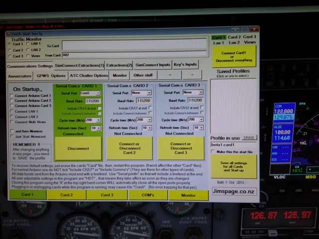
Link2FS is a program put out by a guy named Jim who lives in New Zealand. It allows people to build hardware based on Arduino micro controllers to interface with FSX or P3D flight simulators. Jim has stopped public work on Link2FS so no updates are available for future simulator updates like P3D V4.
LUA is a scripting language that FSUIPC can use to access and change information in FSX and P3D.
LUA can do everything that Link2FS can do and more. Some downsides to LUA are the learning curve and the requirement to have the registered version of FSUIPC. However, if you are a Flight Sim Geek you should probably already have the registered version of FSUIPC. Another downside is there are very few examples of LUA coding for FSUIPC available on the internet, let alone detailed instruction on how the code works. This is something that I hope to help rectify.
Where To Start?
I was going to assume that the reader of this has a working Arduino device like a Radio using Link2FS.
I have reconsidered and decided to cater this tutorial to the novice as well.
Hence, this tutorial only covers push buttons, no encoders or displays yet.
You will need the Registered version of FSUIPC.
FSUIPC comes with some PDF documents that can be very beneficial if not required viewing to program your LUA script. These PDFs are, but not limited to: FSUIPC Lua Library, FSUIPC4 Offset Status, The 2016 List of FSX and P3D Controls, Offset Mapping for PMDG 737NGX and Offset Mapping for PMDG 777X.
There is another program that is nearly required for finding Control Codes in the simulator and Variables in aircraft in order to manipulate them. This program is called LINDA. LINDA has a number of functions in it but we are primarily interested in the LINDA Tracer function with the LINDA Console. LINDA can be very confusing at first, but hopefully I can cover that in another tutorial.
Tutorial 001_a
This tutorial only covers one main thing, one way communication.
It sends data from Arduino to the LUA script in order to change the COM1 radio Standby frequency up or down.
That’s it.
Learning to crawl.
What you will need:
* An Arduino. (Any make should do, UNO, Mega, Leonardo or any of their clones.)
* Two push button switches. (Normal Off, Push On is preferred)
* MicroSoft FSX or Lockheed Martin Prepar3d (P3D)
* The appropriate registered version for your sim of Pete Dowson’s FSUIPC http://www.schiratti.com/dowson.html
* Two files (LUA_Arduino_Tutorial_001_a.ino) and (Tutorial_001_a.lua) located in this zip
NOTE: Both files include extensive instructions in remarks, some of which duplicate what is said here. You can also copy the code directly from this page. I would highly recommend that you download and install Notepad++ for viewing the code and instructional remarks. Notepad++ is also very useful for writing Arduino and LUA code. When viewing or editing Arduino .ino files in Notepad++, go to the Language Menu and select C++ as the Language to get proper format colors. The LUA files should auto select LUA as language.
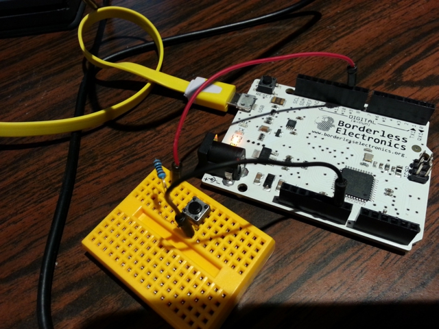
Hardware Instructions:
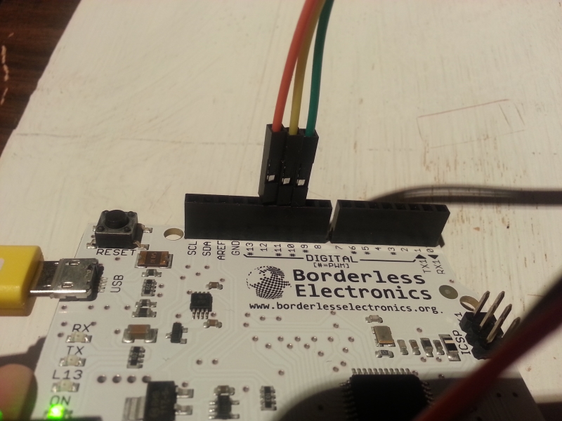
On the Arduino, hook up one switch to pin 7 and ground and the other switch to pin 8 and ground.
After plugging your Arduino into your PC, in the Arduino IDE software under “Tools”,
be sure to select your specific Arduino Board and correct COM Port. (Remember the COM Port, it comes up later)
Upload this sketch to your Arduino.
To test it, In the Arduino IDE Software go to “Tools” and open Serial Monitor.
When you press the pin 7 button “A02” should print on the Serial Monitor.
When you press the pin 8 button “A01” should print on the Serial Monitor.
LUA_Arduino_Tutorial_001_a.ino Code
/* 11-8-2017Arduino LUA FSUIPC Tutorial 001_aLUA_Arduino_Tutorial_001_a.ino This .ino file is an Arduino sketch to teach the very basics of interfacing Arduino built hardware with FSX/P3D using LUA thru the Registered version of FSUIPC. The LUA companion file for this tutorial is Tutorial_001_a.lua. My goal is to write this for the novice to learn. Some of it is rudimentary. Lesson 001_a Communication from Arduino to LUA: This tutorial only does one thing, one way communication. It sends data from Arduino to the LUA script in order to change the COM1 radio Standby freqency up or down. That's it. Learning to crawl. An Evolutionary Process: Many of us started out using Link2FS to interface Arduino with FSX. More advanced needs have lead some of us to use LUA thru FSUIPC. With this in mind, in much of my code I still use the same String Inputs to send info to the Sim that Jim designed in Link2FS. The benefit being that you can take a working Link2FS Arduino Hardware setup and just tailor a LUA script. It can work with either Link2FS or LUA which helps in debugging and trouble shooting. What you will need: * An Arduino. (Any make should do, UNO, Mega, Leonardo or any of their clones.) * Two push button switches. (Normal Off, Push On is prefered) * MicroSoft FSX or Lockheed Martin Prepar3d (P3D) * The appropriate registered version for your sim of Pete Dowson's FSUIPC http://www.schiratti.com/dowson.html Hardware Instructions: On the Arduino, hook up one switch to pin 7 and ground and the other switch to pin 8 and ground. After pluging your Arduino into your PC, in the Arduino IDE software under "Tools", be sure to select your specific Arduino Board and correct COM Port. (Remember the COM Port, it comes up later) Upload this sketch to your Arduino. To test it, In the Arduino IDE Software, go to "Tools" and open Serial Monitor. When you press the pin 7 button "A02" should print on the Serial Monitor. When you press the pin 8 button "A01" should print on the Serial Monitor. */ //***************************************************************** //***************************************************************** // The Variables unsigned long time; // Used in a timer for debouncing a noisy switch unsigned long last_time[20]; // also used for debouncing int debounce_time = 250; // We set to 250ms (1/4 of a sec). This prevents the // switch from "double tapping" inside 1/4 of a sec int current_pin; // As the code cycles thru pins this variable gets assigned that pin int current_pin_state; // The state of an individual pin being processed int current_pin_old_state[20]; // The previous state of an individual pin being processed for comparison // NOTE: the two variables with [n], last_time[20] and current_pin_old_state[20] // These are Array variables. Up here we declare them with the potential to have // 20 diff variables indexed 0-19. So...last_time[0],last_time[1],last_time[2].....on up to last_time[19]. // In this sketch we are using only 2 of the 20. The ones associated with numbers 7 and 8. // I put the array at 20 so that you can experiment and add more lines of code without changing too much. // Copy, Paste, Rinse, Repeat. //***************************************************************** //***************************************************************** void setup() { for (current_pin = 2; current_pin <= 10; current_pin++) // Get all the pins ready as inputs { pinMode(current_pin, INPUT_PULLUP); // By setting the pins as INPUT_PULLUP it makes them all "HIGH" // This lets us use buttons without the need for a "pull up" resistor. // Because we made the pins base state to be HIGH when the button is pressed // the pin will be grounded and fall to LOW. current_pin_old_state[current_pin] = digitalRead(current_pin); // We set the current state of the buttons for comparison later } Serial.begin(115200); // opens serial port, sets data rate to 115200 bps with the PC }//end of setup //***************************************************************** //***************************************************************** void loop() // The main program loop, not a lot here just sets the time variable and launches { // a Function...repeatedly, forever. time = millis(); // This is used to get the current clock time in milliseconds and is // used in debounce. INPUTPINS(); //Calls the function INPUTPINS() where we check the buttons for "presses" }//end of void loop //***************************************************************** //***************************************************************** void INPUTPINS() // Buttons are checked for changes { for (current_pin = 2 ; current_pin <=10; current_pin++) // Going to cycle thru all input pins 2-10 { current_pin_state = digitalRead(current_pin); // Get the "state" of the current pin. As it cycles thru, "current_pin" changes. // "State" is whether the pin is HIGH or LOW depending on if the button is pressed. // The first time thru, digitalRead(current_pin) is seen as digitalRead(2). // The second time thru digitalRead(current_pin) is seen as digitalRead(3) and so on. if (current_pin_state != current_pin_old_state[current_pin])// compare the state of the current pin to its previous state { // if the states are not the same, then continue. //*************************************************************************************** if (current_pin == 7) // If the pin is 7 then continue. { if (time - last_time[current_pin] > debounce_time) // If the time from the loop minus "last_time[7]" is greater than 250ms { // then continue if (current_pin_state == LOW ) // If its LOW then the button has been pressed. { Serial.println ("A02"); // "A02" is the Com1 Standby Mhz up code from Link2FS } last_time[current_pin] = millis(); // Reset "last_time[7]" } } //*************************************************************************************** if (current_pin == 8) // If the pin is 8 then continue. { if (time - last_time[current_pin] > debounce_time) // If the time from the loop minus "last_time[8]" is greater than 250ms { // then continue if (current_pin_state == LOW ) // If its LOW then the button has been pressed. { Serial.println ("A01"); // "A01" is the Com1 Standby Mhz down code from Link2FS } last_time[current_pin] = millis(); // Reset "last_time[8]" } } //*************************************************************************************** }// End of IF Current Pin State Check current_pin_old_state[current_pin] = current_pin_state; // Records the current pin state for comparison the next time thru }// End of 'for' loop }// End of INPUTPINS() Function //********************************************************* //*********************************************************
Instructions To Launch the LUA script:
* Place this file in the Modules folder of your sim with the other FSUIPC files
* Have the COM port of the Arduino handy you will need to enter it on first launch
* In P3D go to Add-ons
* Select FSUIPC
* Select Buttons and Switches Tab
* Press a button on your joystick to assign a launch button
* Tick the “Select for FS control” box
* In the drop down “Control sent when button is pressed”
* Scroll down and select “Lua Tutorial 001 A”
* NOTE: NOT LuaClear, LuaSet, LuaDebug
* You can set another button for “LuaKill Tutorial 001 A”
* Hit OK
* Back in the sim, press the Joystick button that you asigned
* Enter the COM port when requested
* Afterward it should remember the COM port on future launches
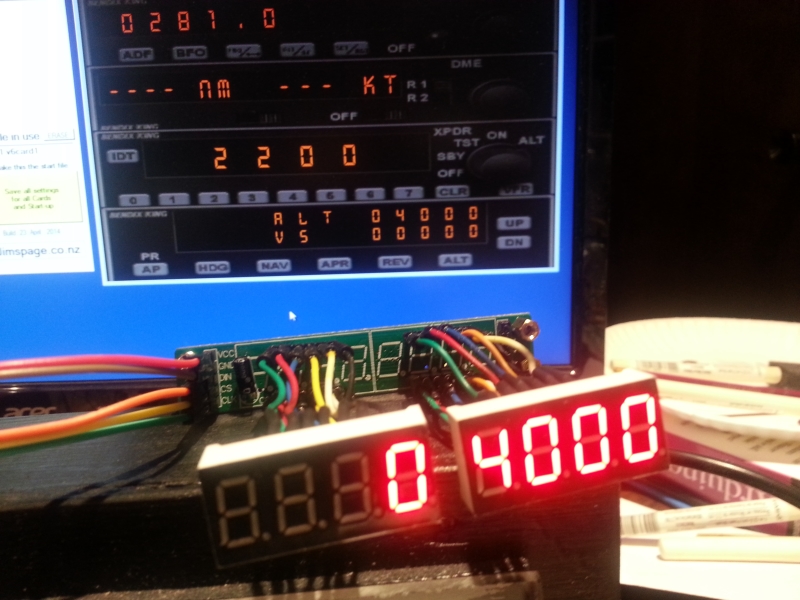
* Press the buttons on the Arduino and Com 1 radio Standby Mhz should go up and down.
Tutorial_001_a.lua Code
--11-8-2017
--http://thegeekforge.com/2017/11/10/arduino-lua-fsuipc-tutorial-001_a/
--
--Tutorial_001_a.lua
--
--This .lua file is script to teach the very basics of interfacing
--Arduino built hardware with FSX/P3D using LUA thru the Registered version of FSUIPC.
--The Arduino companion file for this tutorial is LUA_Arduino_Tutorial_001_a.ino.
--My goal is to write this for the novice to learn. Some of it is rudimentary.
--
--Lesson 001_a Communication from Arduino to LUA:
--This script only does one thing. It receives data from Arduino
--in order to change the COM1 radio Standby freqency up or down.
--That's it.
--Learning to crawl.
--
-- You Will Need:
-- The appropriate registered version for your sim of Pete Dowson's FSUIPC
-- http://www.schiratti.com/dowson.html
--
-- Instructions To Launch the script:
-- * Place this file in the Modules folder of your sim with the other FSUIPC files
-- * Have the COM port of the Arduino handy you will need to enter it on first launch
-- * In P3D go to Add-ons
-- * Select FSUIPC
-- * Select Buttons and Switches Tab
-- * Press a button on your joystick to assign a launch button
-- * Tick the "Select for FS control" box
-- * In the drop down "Control sent when button is pressed"
-- * Scroll down and select "Lua Tutorial 001 A"
-- * NOTE: NOT LuaClear, LuaSet, LuaDebug
-- * You can set another button for "LuaKill Tutorial 001 A"
-- * Hit OK.
-- * Back in the sim, press the Joystick button that you asigned
-- * Enter the COM port when requested.
-- * Afterward it should remember the COM port on future launches
-- * Press the buttons on the Arduino and Com 1 radio Standby Mhz should go up and down.

------------------------------------------------------------------
---- Variables ---------------------------------------------------
------------------------------------------------------------------
port_file = "Tutorial_001_a_PORT.txt"
speed = 115200
handshake = 0
----End of Variables section -------------------------------------

------------------------------------------------------------------
---- Com Port set up and recording.  AKA the Magic section -------
------------------------------------------------------------------
-- Not going to go into this section other than to tell you it will
-- prompt you for the arduino com port and record it in a text file
-- that it places in the Modules folder.
file = io.open(port_file, "r")
if file == nil then
	port_number = "10"
	file = io.open(port_file, "w")
	io.output(file)
	io.write(port_number)
	io.close(file)
	Arduino_Com_Port = com.open("COM"..port_number, speed, handshake)
else
	port_number = file:read (2)
	--ipc.display(port_number)
	io.close(file)
	Arduino_Com_Port = com.open("COM"..port_number, speed, handshake)
end
if Arduino_Com_Port ~= 0 then
	ipc.display("Arduino Com Port "..port_number.." Open",5)

else
	ipc.display("Could not open ARDUINO Com Port")
	ipc.sleep(2000)
	port_number = ipc.ask('\n'..'\n'..'\n'..'\n'..'\n'..'\n'..'\n'..'\n'.." Enter the Arduino Com Port for Your RADIO")
	file = io.open(port_file, "w")
	io.output(file)
	io.write(port_number)
	io.close(file)

	Arduino_Com_Port = com.open("COM"..port_number, speed, handshake)

	if Arduino_Com_Port == 0 then
		ipc.display("Could not open ARDUINO Com Port",5)

		ipc.exit()
	else
		ipc.display("Arduino Com Port "..port_number.." Open",5)

	end
end
---- End of Magic section ----------------------------------------


------------------------------------------------------------------
---- Functions ---------------------------------------------------
------------------------------------------------------------------
-- Only one function in this script.
-- When data comes in from the Arduino, it gets sent to this
-- function.  When it finds one of the strings in "" it does that
-- ipc.control.
function Arduino_Data(Arduino_Com_Port, datastring, length)

	---- COM1 Standby Freq -------------------------------------
	if (string.find(datastring, "A02")) then
		ipc.control(65637,0)  --This is the control to move Com1 Stby Mhz up
	end
	if (string.find(datastring, "A01")) then
		ipc.control(65636,0)  --This is the control to move Com1 Stby Mhz down
	end
	if (string.find(datastring, "A04")) then
		ipc.control(65639,0)  --This is the control to move Com1 Stby Khz up
	end
	if (string.find(datastring, "A03")) then
		ipc.control(65638,0)  --This is the control to move Com1 Stby Khz down
	end
			-- What are control numbers in "ipc.control" and where do I find them?
			-- In the FSUIPC Docs there is a PDF with a list.
			-- Also a program called LINDA has function called Tracer.
			-- Tracer has Controls as well as Lua Variables for specific Aircraft
			-- Another way to manipulate the sim is thru offsets. Some are read only,
			-- others you can write to.
end  -- function end
---- End of Functions section -----------------------


-----------------------------------------------------
---- Events -----------------------------------------
-----------------------------------------------------
-- Events are awesome. They dont require a continuous loop to work.
-- They just sit back and wait for a trigger and then spring into action.
-- Events must go at the bottom of the script. Why? Google it.

event.com(Arduino_Com_Port, 50,1, "Arduino_Data")
	-- This is event.com, it listens for data on the Arduinos Com port.
	-- The 50 and 1 are the max and min characters accepted
	-- The data is then passed to the "Arduino_Data" function above.


---- End of Events section --------------------------
A Challenge for the Newbie
You may have notice in the LUA file, that there is code to also change the Khz of the COM1 Standby radio.
However, I did not include the corresponding code in the Arduino Sketch.
I left that for the novice to experiment with.
Just hook up a couple more buttons to the Arduino on some of the other pins between 2 and 10.
Then add the extra code to the Arduino Sketch to make it work.
You won’t have to change anything on the LUA script.
Trouble Shooting
If you happen to have more than one Arduino connected to your PC and you accidentally enter the incorrect COM Port of the Arduino when launching the LUA script, it can cause the script to connect to the wrong Arduino. To fix this and get connected to the correct Arduino, you can delete the “Tutorial_001_a_PORT.txt” file from your Modules folder and relaunch the script and then enter the correct port when prompted. Alternatively, you can manually edit that file and put in the correct COM Port number.
Apologies
I apologize for any typos errors and omissions.
If you see any errors, leave a comment and I might fix it.
I may periodically edit this to improve quality.
~Fess
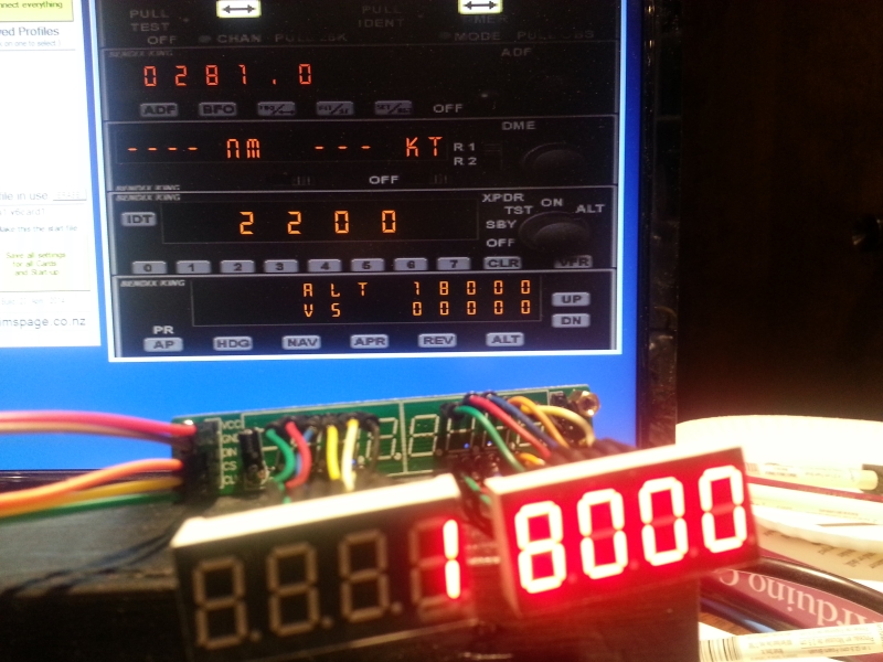
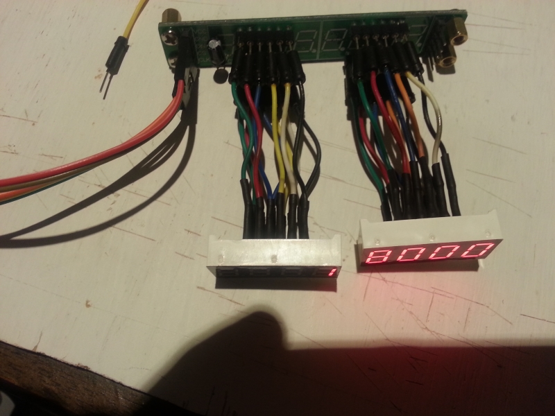
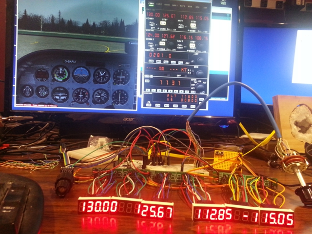
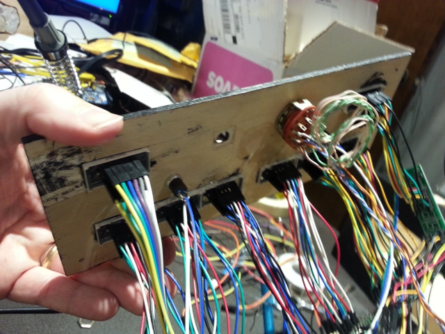
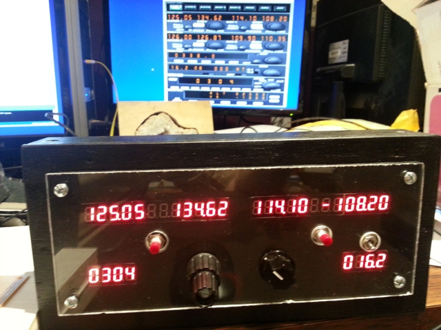
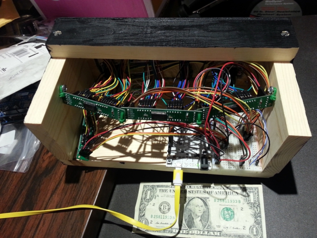
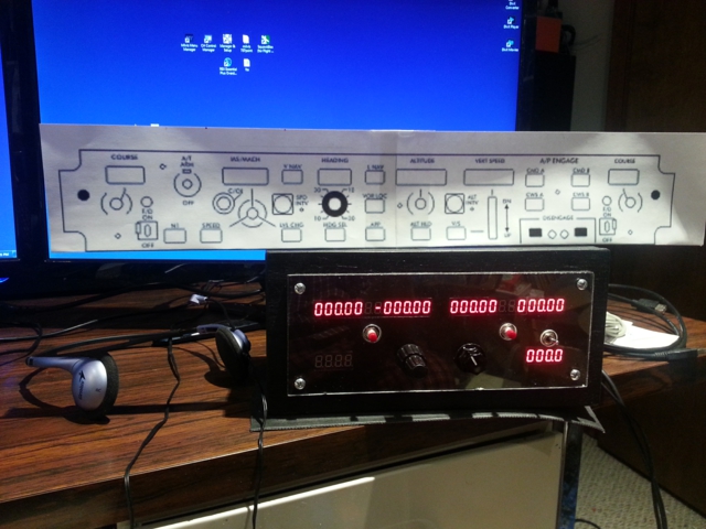
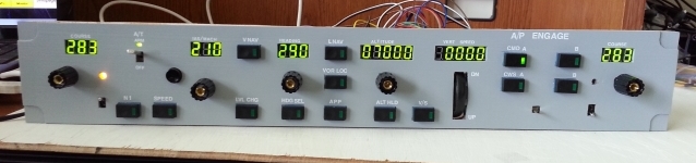
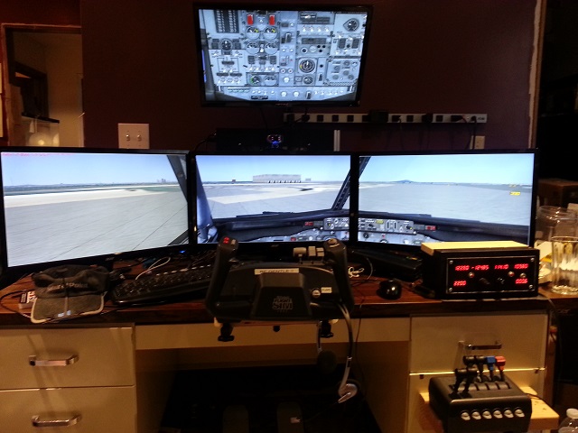 If you are an ate-up, Flight-Sim geek, then you may have a setup similar to that above.