August 5, 2014
This project was conceived and started with the ordering of parts around Sept-Oct, 2013.
Functional construction and coding was completed mid Nov, 2013.
A friend and I worked on this together. He was also building a radio. His was a bit different than mine with a smaller footprint for a fighter cockpit setup.
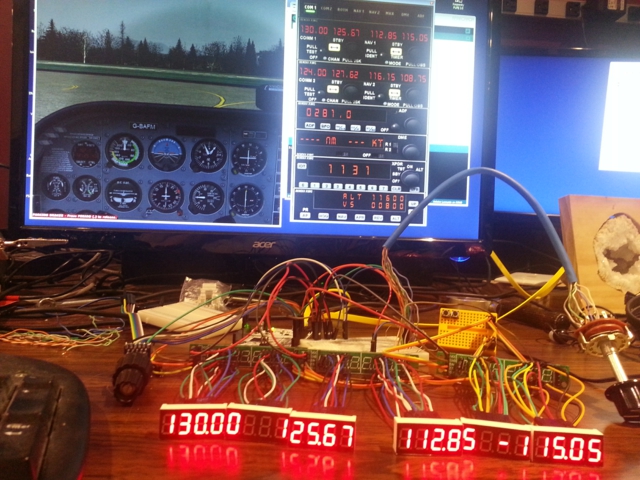
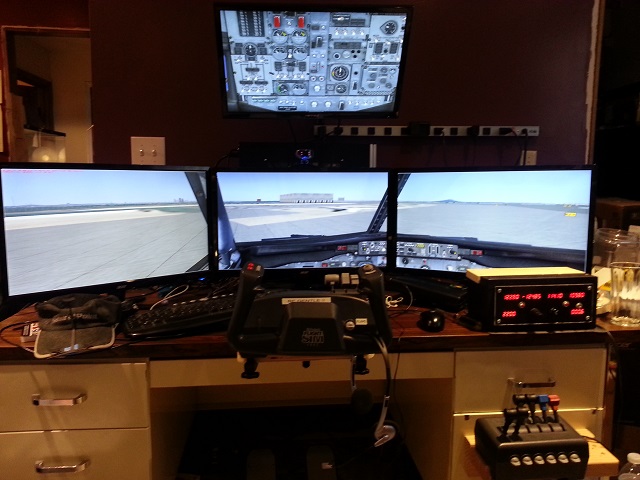 If you are an ate-up, Flight-Sim geek, then you may have a setup similar to that above.
In the picture we have MicroSoft Flight Simulator X (FSX), CH Yoke, CH Throttle Quadrant, CH Rudder Pedals (on the floor), three 24 inch displays in span view, a single 21.5 inch overhead display, TrackIR (head tracking device), and on the right side of the desk, lit up with red 7-segment displays, is a custom built Radio Stack of which this article is about.
 Here is a close up with a $1 bill for scale.
Acknowledgements
This project would not have been possible without a software interface program that allows Arduino cards to talk to FSX. The program is called Link2fs and was written by a man named Jim who lives in New Zealand. I have been following Jim at jimspage.co.nz for a number of years. He has built at least two incarnations of a flight simulator motion platform.
A motion platform is the dream.
I had dabbled a bit, in the past, with Arduino. Once I built an interface for a recumbent stationary bike-to-PC using an Arduino, a magnetic reed switch, and a game controller. It allowed the user to run in first person shooter games by pedaling the bike.
When I read that Jim had discovered Arduino and he had written the Link2FS interface software to talk to FSX, I had to give it a shot.
Disclaimer
Let me warn you…
If you start down this path of building interface devices for Flight Simulator, it is a dark path and it never ends. Each new buzzer, bell, or whistle that you make will give you a “discovery and accomplishment” high. It will make you feel as if there is nothing you can’t do. But the high is fleeting. It does not last. You will soon become discontent with the status quo. Then you start thinking, “Well it would be easy to add this or to add that.” It won’t stop until you have a full scale replica cockpit consuming substantial square footage of living space in your home. If your family is lucky, you prefer small general aviation aircraft over commercial jets.
First We Crawl
The first thing I needed to do before ordering some of the more pricey parts was some proof of concept testing. I had downloaded Jim’s software and had confirmed that it did indeed connect to FSX and could change things, like radio frequencies.
Next, I hooked up a simple push button switch on an Arduino clone and modified some of Jim’s example code, to make the switch change one of the radio frequencies in one direction.
That’s all it did, you press the button and the Mhz go up by one tick.
As simple as it was, it gave me the first rush.
One of the other things I did, not pictured, is wire up some LEDs as Landing Gear status lights and used some more of Jim’s sample code to make them work. By experimenting with the Link2FS software and different Arduino code, it allowed me to learn more about the nuance and communication relationship of FSX to Link2FS and Link2FS to Arduino.
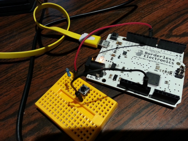 Arduino Leonardo Clone with simple push button switch.
Pictured below is a snapshot of an older version of Jim’s Link2fs_multi program. It is the program that interfaces FSX to Arduino. It is the middle man, that sends and receives from FSX and also sends and receives from Arduino. The “multi” version allows you to control multiple Arduinos with one instance of the Link2fs program. Need more Arduinos than one instance can handle? Not a problem. You can also run multiple instances of Link2fs_Multi.
FSX <-> Link2FS <-> Arduino.
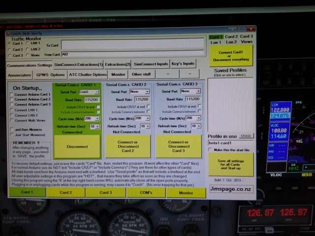 Link2fs_Multi, interface program for FSX to Arduino.
The Acquisition
Now that I have proved that it is possible to change things in FSX from an Arduino, it is time to start finding components to build a Radio Stack.
Many different aircraft avionics utilize “Dual Concentric Rotary Encoders”. These are basically 2 dials in one. Elma makes a good one in the E37. Unfortunately, they aren’t cheap and they aren’t easy to come by. There is one guy on the planet, that I know of, that sells them in single quantities and that’s Leo at leobodnar.com in the UK. At the time of this writing one E37 with knobs, from Leo, shipped to the US via Royal Mail Airmail would be $40.26 USD. In Dec of 2013, I had enquired at Elma to see what I could get if I wanted to buy bulk. At 100 units they would cost $17.50 per each not including knobs.
I bought three E37s from Leo, one for me, one for a friend and one for a spare or future project.
Elma E37 Dual Concentric Rotary Encoders.
Since I didn’t want to drop big money for multiple Encoders, I decided to use a Rotary Switch as a function selector on the Radio. You dial the function you want with the switch and then use the encoder to change the frequency.
Functions that I coded in were: COMM/NAV 1, COMM/NAV 2, TRANSPONDER, ADF, and a limited AUTO PILOT function for experimentation.
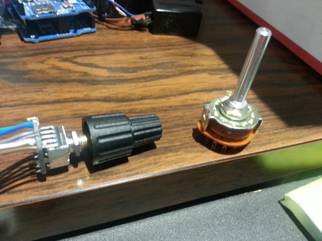 Rotary Encoder on the left. Rotary Switch on the right.
The Elma E37 Rotary Encoders are not plug-and-play. They come with a small Printed Circuit Board (PCB) that needs to be soldered to the encoder. The PCB has marked pinout holes in it that allows you to also solder wire leads to it.
When I first coded the Arduino to work with the Encoder, again taking Jim’s sample code and modifying it for my purpose, I got the accomplishment rush again, “I am turning a knob and the frequencies in the sim are changing! So cool, so cool!” When I showed it to my friend, his response was a satisfied, “Ok, that’s perfect. I’m done.” As if that is all he needs to make him happy, he needs no more. But no, that was just his first “high“. We didn’t even have the 7-Segment Displays yet.
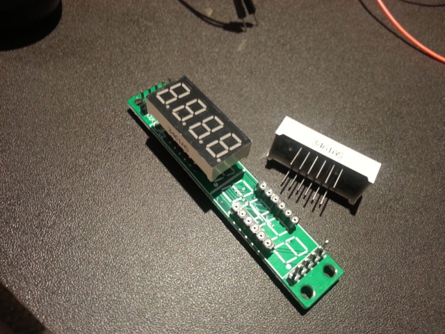 MAX7219 8-Digit 7-Segment Tube Display Module
While looking for a 7-segment LED display solution, I came across a number of possibilities.
Some were serial driven modules that had 16 digits. I had also seen other folks actually drive multiple single digit 7-segment displays by multiplexing outputs on Arduino. An incredible accomplishment with an insane amount of wires but way too complex for me. Plus it uses too many Arduino input/output pins.
I finally stumbled onto the MAX7219 8-Digit 7-Segment Tube Display Module. The chip on the Module is the MAX7219 which is the driver for the displays. In short, it receives a serial instruction, displays what the instruction told it to display, and holds that display until told to do otherwise.
These displays work with the LedControl library for Arduino.
The beauty of these display modules is that they are comprised of two 4-digit displays that are not soldered to the board. They are in sockets. This got me to think that I can tether these displays with wires and place them any where I want to on my radio without the PCB getting in the way.
The other great thing about these displays is that you can chain up to eight of them together and only have to use three pins on the Arduino.
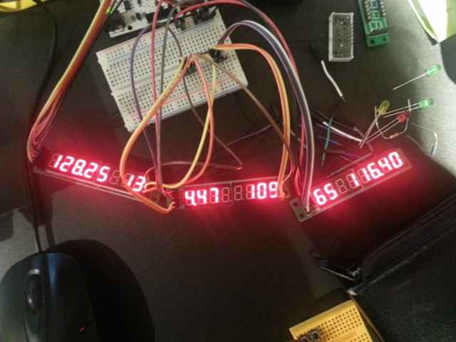 3 MAX7219 Display Modules chained together for testing, pre tethering.
 Here are 3 MAX7219 Modules with the 7-Segment Displays tethered away from the boards.
Also pictured is the Rotary Encoder, Rotary Switch and Arduino and experiment board for wire junctions behind the Modules.
Box It Up
The hardware and software are now working together. We need to get all of those wires in a box.
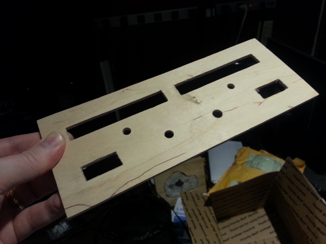 This is the face plate that my friend helped me come up with.
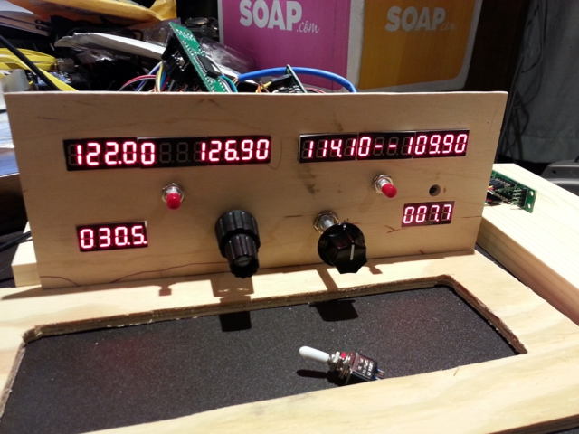 The rough fit. I added a 4th MAX7219 Display Module for Transponder and DME.
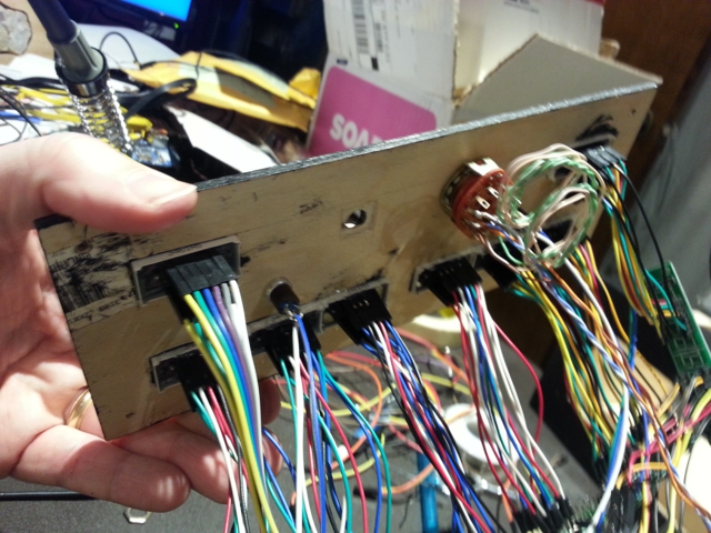 The back side fitting after paint had been applied.
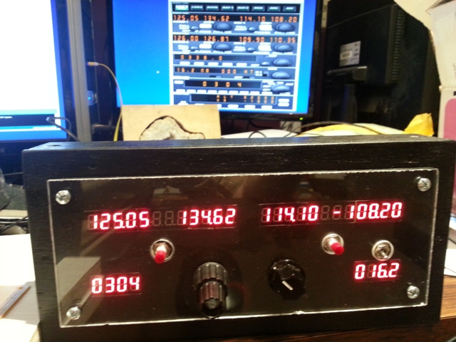 Lexan cover for the face plate.
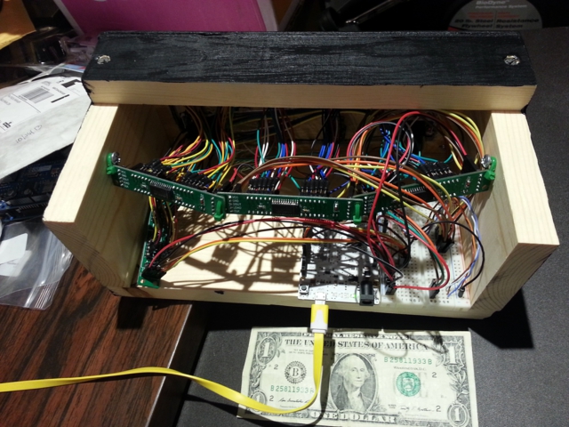 Backside with a dollar bill for scale.
Acceleration on the Encoder and updated functions.
Notes
After months of use and testing, some things I would do differently…
The female end of the tether wires on the 7-segment displays doesn’t cut the mustard. Sometimes, from movement, the segments on the displays will flicker because of the female ends slipping. A little jostling and they work. To do it better, the tether wires need to be soldered to the 7-segment displays. The other end of the tether wire can still be plugged into the MAX7219 Module without problem.
I am planning on designing and building a new Radio Stack with multiple displays and multiple encoders instead of sharing the main display and encoder with multiple radios.
The Sickness Continues…
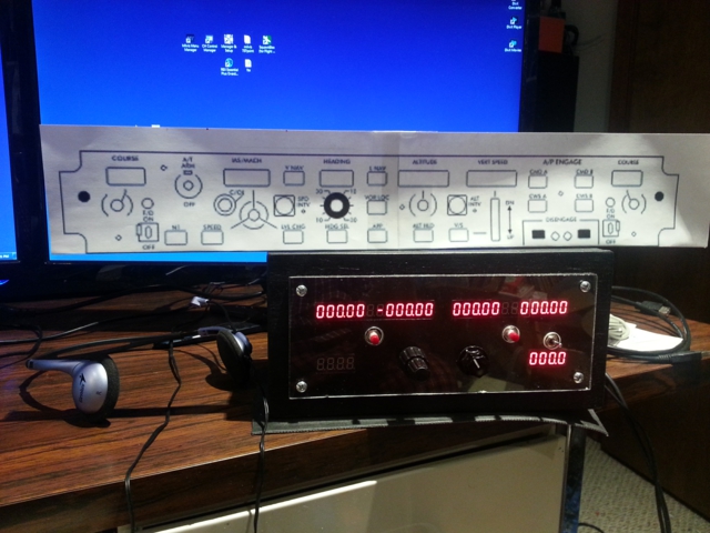 Scale print out of the next project, a Mode Control Panel (MCP)/Auto Pilot for a Boeing 737.