November 17, 2014
A few folks have asked me how to connect a MAX7219, 8 Digit, 7 Segment, Tube Display Module to an arduino and code it to display information from Flight Simulator X (FSX) via Link2FS.
Below are pictures and explanation of one way to set this up.
At the bottom of this article is a working but limited Arduino Sample Sketch that will only display the Autopilot Altitude Set from FSX via Link2FS. The Arduino Code has been mostly stripped down to this one function for simplicity and is remarked heavily for educational purposes.
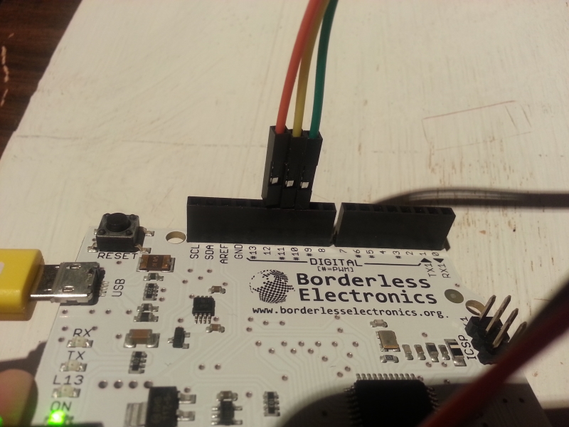
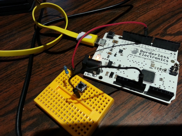
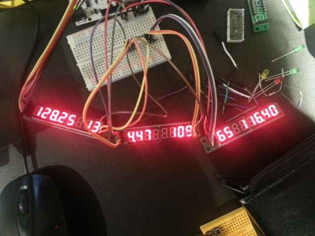
In the picture above I am using an Arduino Leonardo Clone. An Uno or Mega will also work.
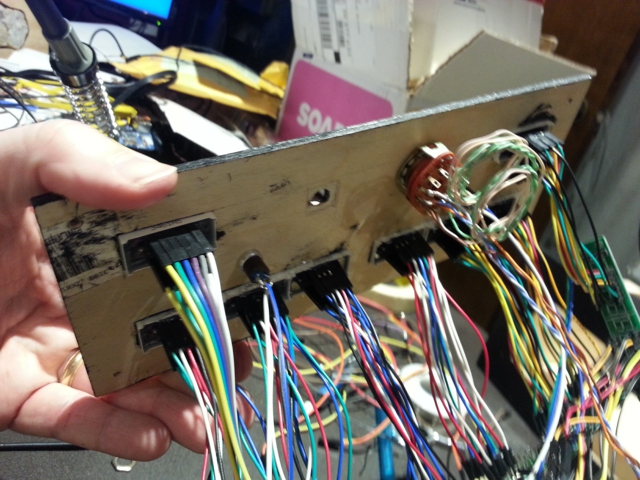
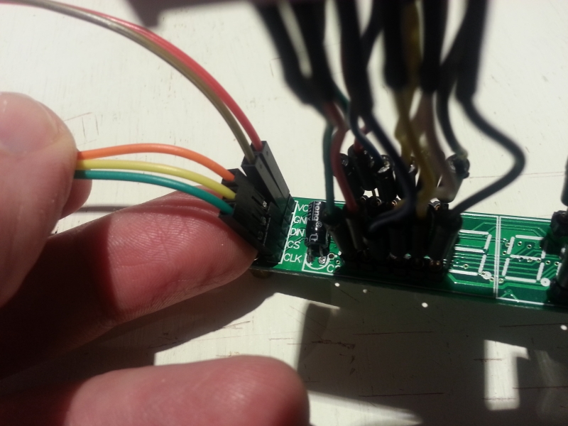
To connect the MAX7219 to the Arduino, we use 5 wires connected to the 5 pins on the left side of the module. Three of them are for communication and two are for 5 Volt and Ground connections.
In this particular example I use pins 10, 11, and 12. If you compare the wire colors in the picture below with the picture above, you will see Orange, Data (DIN) is connected to pin 12, Yellow, Load (CS) is connected to pin 11, and Green, Clock(CLK) is connected to pin 10.
Red and Brown are connected to 5Volt (VCC) and Ground (GND), respectively.
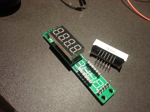
The Modules have another set of pins on the right side of the Printed Circuit Board (PCB), that are labeled nearly identical to the left side. The right side pin labels are on the backside of the PCB. They are VCC, GND, DOUT, LOAD, CLK. If you have more than one module that you want to “chain” together then you do it through these pins. The second module’s left side, DIN, CS, and CLK would go to the first modules right side DOUT, LOAD, and CLK.
NOTE: Do NOT chain the VCC 5Volt and GND from one module to another. As I understand it there is a diode in each module that will drop the voltage on the out going side. It may work ok with 2 or 3, but if you chain more you may be looking at dimming digits or failure to function. So, it’s easy enough to run the 5Volt and Ground to a common bus from the Arduino.
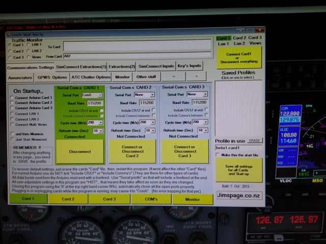
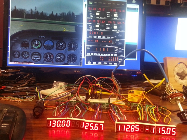
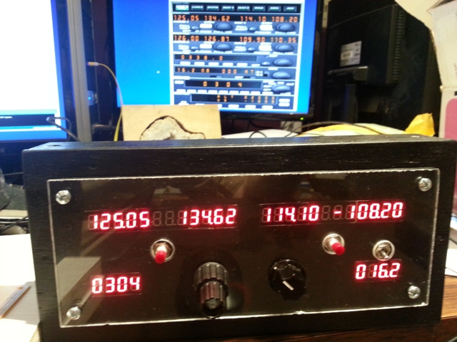
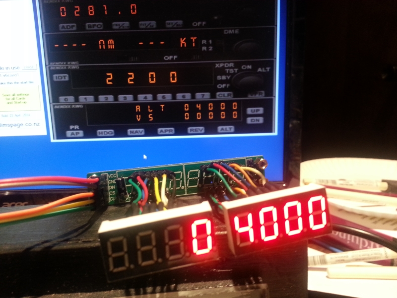
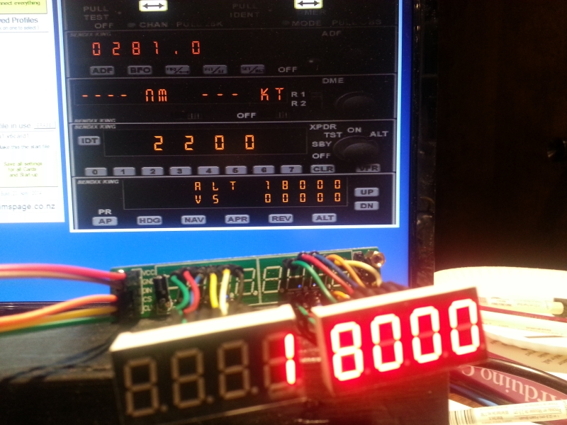
In the picture below you can see we are connected to Link2FS and receiving the Autopilot Altitude Set as it is present on the display.
Link2FS Output to Arduino
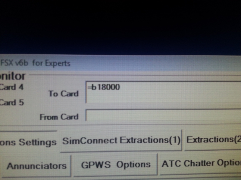
In the above picture you can see what Link2FS sends to the Arduino when the Autopilot Altitude Set is at 18000.
=b18000
First the Arduino Code looks for the “=”.
After finding the “=” it checks the next character and find a “b”.
The “b” tells the “Switch Case” in the code to start storing and display the Autopilot Altitude set “18000”.
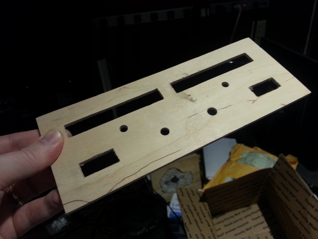
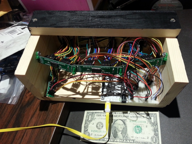
Hardware Notes:
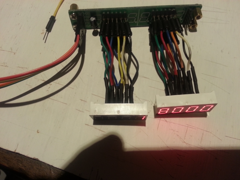
The picture above is just to show how the displays can be tethered away from the module. On my first go, I used male/female jumpers. I found that the female connection to the displays would sometimes become loose and subject to vibration making the connection intermittent. This would result in some or parts of the display digits to flicker or go off completely. Jostling the wires would cause it to work again. This picture has soldered connections on the display side, with heat shrink covering.
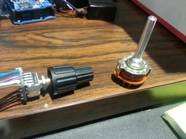
The Jumpers and Heat Shrink
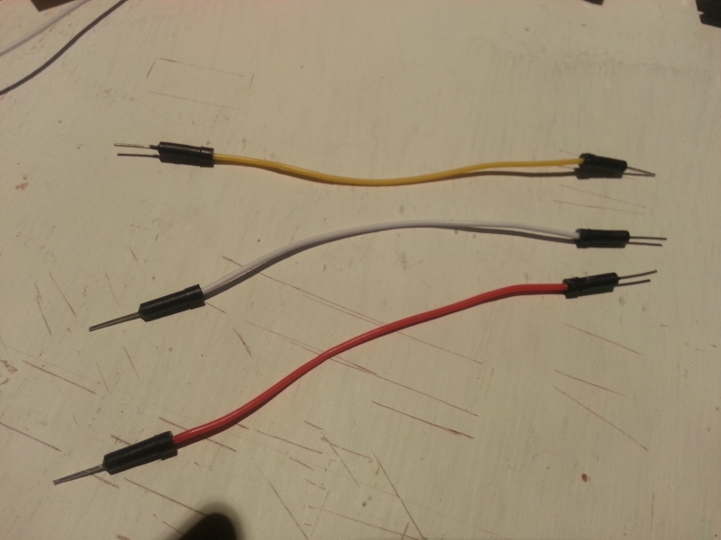
Pictured above is the type of jumper wires needed to tether the displays away from the module.
The leads have round male connectors.
NOTE: Dupont brand wire jumpers with square male connectors that work fine with Arduinos, will not fit the female connection on the Max7219 display module.
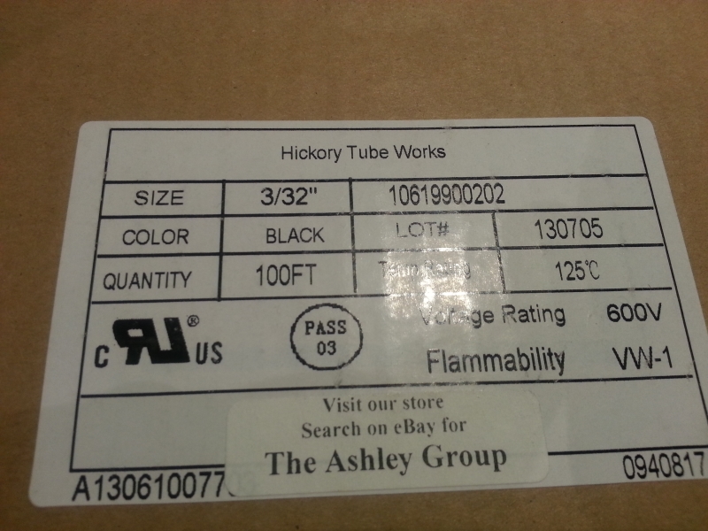
The picture below:
If you find the need to do a lot of soldering and cover the connections with heat shrink, it is far cheaper to buy heat shrink by the 100ft spool.
I used 3/32 for the above wires. I found the 100 foot spool on ebay for about $13 US.
Here is the Code with a lot of Remarks
I tried to format it for understanding.
/*
This is a simple demonstration of code to Display information on a MAX7219 8 Digit 7 Segment Tube Display Module.
The Information is extracted from Flight Sim X via a program called link2fs_multi and then sent to the arduino.
There are snippets in this code that came from Jim, the author of Link2FS.
Find him at jimspage.co.nz. Also, in the mycockpit.com forums under link2fs.

This example will only work with FSX's default Auto Pilot.
Some planes like PMDG's 737 does not use FSX's default variables.
I use an Array variable to store the Auto Pilot Altitude Set Display.
Its probably not necessary, but its what I used in my Radio Box for quicker updates when using
shared displays with a Mode/Function Selector knob.
              *****************************************
              ***** Info on how the Displays work *****
              *****   This is an excerpt from my  *****
              *****        Radio Box Code         *****
              *****************************************
      led_Display_1.setDigit(0,7,Com1Active[0],false);    // setDigit(0,7,Com1Active[0],false) The 0 is the first display, 7 is the first character in the
      led_Display_1.setDigit(0,6,Com1Active[1],false);    // display, Com1Active[0] is the stored Integer to be displayed, false is no decimal point.
      led_Display_1.setDigit(0,5,Com1Active[2],true);     // "true" puts in the decimal point
      led_Display_1.setDigit(0,4,Com1Active[3],false);    // setDigit is for putting in numbers
      led_Display_1.setDigit(0,3,Com1Active[4],false);    // You can also use setChar for putting in some letters
                                                          // character, symbols, and ' ' space.
                                                          // NOTE: setChar has to use single quote 'A'
                                                          // Double quote "A", is for Strings and wont work.

      ****************** The 300 Level Remarks ****************************************
       In the "300 Level Class", you can use setRow to light one of the 7 segment
       displays using binary or hex equivalent. It would look like this:
       led_Display_1.setRow(1,4,B00110000,false) that would display the number 1.

                __A_      The segments on my displays are lettered A thru H
              F|    |B    However, using the setRow with Binary the H (decimal point) comes first.
               |__G_|             If you want an 8 with no decimal...
              E|    |C             H A B C D E F G
               |__D_|.H          B 0 1 1 1 1 1 1 1   = 8
                                 B 0 1 1 1 0 0 0 0   = 7

      *********************************************************************************

*/


#include "LedControl.h"
                               // ******   LedControl Library is required to drive the MAX7219 7 segment LED displays.  *******
                                                    // led_Display_1 is the variable name of my set of displays chained
LedControl led_Display_1 = LedControl(12,10,11,8);  // together running off of pins 12,11,10.
                                                    // Pin 12 is the DataOut
                                                    // Pin 11 is Load or CS
                                                    // Pin 10 is clock.
                                                    // The 8 is for how many displays you have to chain.
                                                    // I have 4 but put 8 incase of expansion. It cost no memory.
                                                    // You can run any pins you want in the instruction,
                                                    // just plug the module in correctly.
                                                    // LedControl(Data,Clock,Load,Displays)
                                                    // I used 12,10,11 so I could have a straight ribbon connection
                                                    // from the module without crossing leads.


int CodeIn;      // used on all serial reads from Jim's code
String Digit;    // Variable as a string to take from getChar()
int Count;       // This variable used in loops in the EQUALS() function
int AP_alt_set[5];   // AP_alt_set[5] is an array of the 5 digits that are the Auto Pilot Altitude Set


//**********************************************************
//*************( START of void setup() )********************

void setup()
{
    //The MAX72XX is in power-saving mode on startup, we have to do a wakeup call
    delay (500);
    led_Display_1.shutdown(0,false);      // I have 4 displays, these start them up
    // delay (500);                          // I put the delay in so they all dont start drawing
    // led_Display_1.shutdown(1,false);      // current at the same time.
    // delay (500);                          // I had an issue with running on only USB power and getting a display glitch.
    // led_Display_1.shutdown(2,false);      // The delay seems to have fixed this issue.
    // delay (500);
    // led_Display_1.shutdown(3,false);

    // Set the brightness to a lower than medium values
    led_Display_1.setIntensity(0,8);
    // led_Display_1.setIntensity(1,8);
    // led_Display_1.setIntensity(2,8);
    // led_Display_1.setIntensity(3,8);

    // and clear the display
    led_Display_1.clearDisplay(0);
    // led_Display_1.clearDisplay(1);
    // led_Display_1.clearDisplay(2);
    // led_Display_1.clearDisplay(3);

    Serial.begin(115200);
}
//**************( END of void setup() )********************
//*********************************************************


//*********************************************************
//*************( START of void loop() )********************

void loop()
{
    if (Serial.available())
    {
        CodeIn = getChar();
        if (CodeIn == '=')
        {
            EQUALS();              // The first identifier is "="
        }
   // if (CodeIn == '<') {LESSTHAN();}// The first identifier is "<"
   // if (CodeIn == '?') {QUESTION();}// The first identifier is "?"
   // if (CodeIn == '/') {SLASH();}// The first identifier is "/" (Annunciators)
  }
}
//*****************( END of void loop )********************
//*********************************************************


//*********************************************************
//************( START of getChar() Function )**************

char getChar()// Get a character from the serial buffer
{
  while(Serial.available() == 0);   // wait for data
  return((char)Serial.read());      // Thanks Doug
}
//***************( END of getChar Function )***************
//*********************************************************


//*********************************************************
//*************( START of EQUALS() Function )**************

void EQUALS()               // The first identifier was "="
{
    CodeIn = getChar();     // Get another character
    switch(CodeIn)          // Now lets find what to do with it
    {
        case 'b':           //  AP altitude set
            Count = 0;               // clear the Count
            while (Count < 5)        // we will count to 5 from 0 to 4
            {
                Digit = "";          // clears the string variable Digit
                Digit += getChar();  // Makes the string Digit what ever getChar() is holding

                AP_alt_set[Count] = Digit.toInt(); // Turns the string Digit into an Integer and
                                                   // then stores it in the Array AP_alt_set[] 0,1,2,3,4
                Count++;
            }

            led_Display_1.setDigit(0,4,AP_alt_set[0],false);   // First digit of Alt Set is displayed
            led_Display_1.setDigit(0,3,AP_alt_set[1],false);   // Second digit of Alt Set is displayed
            led_Display_1.setDigit(0,2,AP_alt_set[2],false);   // Third digit of Alt Set is displayed
            led_Display_1.setDigit(0,1,AP_alt_set[3],false);   // Fourth digit of Alt Set is displayed
            led_Display_1.setDigit(0,0,AP_alt_set[4],false);   // Fifth digit of Alt Set is displayed
                                                               // false denotes NO decimal point
        break;
/*
    ******************************************************************************
    *********  REMARKED OUT EVERYTHING EXCEPT AUTO PILOT ALTITUDE SET ************
    *********    IF YOU TRY TO USE THE BELOW CODE IT WILL NOT WORK    ************
    *********        IT HASNT BEEN FULLY SET UP IN THIS SAMPLE        ************
    ******************************************************************************
        case 'c':    //  AP vertical speed set
            Count = 0;
            while (Count < 4)
            {
                Digit = "";
                Digit += getChar();

                if (Count == 0)
                {
                    if (Digit == "-")
                    {
                        AP_vs_minus = '-';
                    }
                    else
                    {
                        AP_vs_minus = ' ';
                    }
                    Digit = "";
                    Digit += getChar();
                }

                AP_vs_set[Count] = Digit.toInt();
                Count++;
            }
                led_Display_1.setChar(2,4,AP_vs_minus,false);
                led_Display_1.setDigit(2,3,AP_vs_set[0],false);
                led_Display_1.setDigit(2,2,AP_vs_set[1],false);
                led_Display_1.setDigit(2,1,AP_vs_set[2],false);
                led_Display_1.setDigit(2,0,AP_vs_set[3],false);
        break;

        case 'd':    //  AP heading set
            Count = 0;
            while (Count < 3)
            {
                Digit = "";
                Digit += getChar();

                AP_hdg_set[Count] = Digit.toInt();
                Count++;
            }
            if (AP_hdg_set[0]==0 and AP_hdg_set[1]==0 and AP_hdg_set[2]==0)
            {
                AP_hdg_set[0]=3; AP_hdg_set[1]=6;
            }
            led_Display_1.setDigit(1,6,AP_hdg_set[0],false);
            led_Display_1.setDigit(1,5,AP_hdg_set[1],false);
            led_Display_1.setDigit(1,4,AP_hdg_set[2],false);
        break;

        case 'e':    //  AP course set
            Count = 0;
            while (Count < 3)
            {
                Digit = "";
                Digit += getChar();

                AP_crs_set[Count] = Digit.toInt();
                Count++;
            }
            if (AP_crs_set[0]==0 and AP_crs_set[1]==0 and AP_crs_set[2]==0)
            {
                AP_crs_set[0]=3; AP_crs_set[1]=6;
            }

            led_Display_1.setDigit(0,7,AP_crs_set[0],false);
            led_Display_1.setDigit(0,6,AP_crs_set[1],false);
            led_Display_1.setDigit(0,5,AP_crs_set[2],false);

            led_Display_1.setDigit(3,6,AP_crs_set[0],false);
            led_Display_1.setDigit(3,5,AP_crs_set[1],false);
            led_Display_1.setDigit(3,4,AP_crs_set[2],false);
        break;

       //etc etc etc
       // You only need the "Case" testing for the identifiers you expect to use.
    ******************************************************************************
    *********  REMARKED OUT EVERYTHING EXCEPT AUTO PILOT ALTITUDE SET ************
    ******************************************************************************  */
    } // ***  End of Switch Case ***
}
//***************( End of EQUALS() Function )**************
//*********************************************************
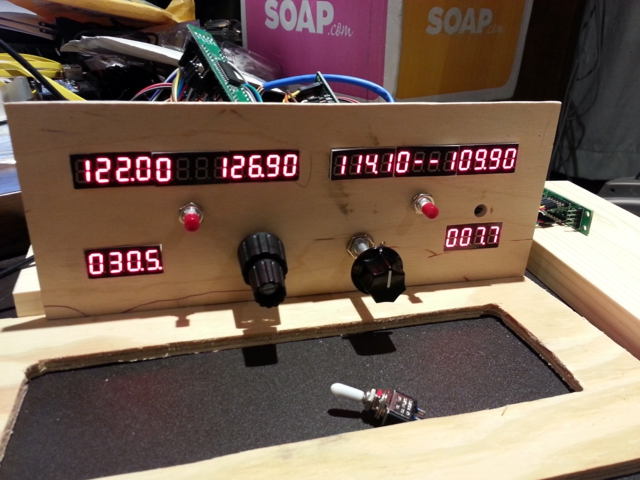
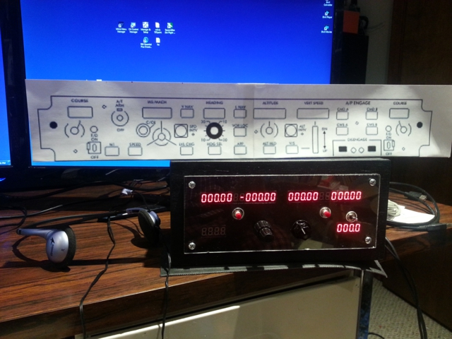
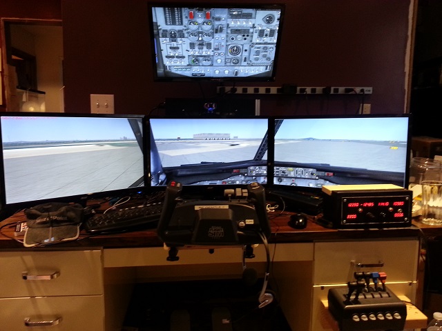 If you are an ate-up, Flight-Sim geek, then you may have a setup similar to that above.