8/12/2020
A Public Service Announcement:
To hide the Yoke in Aeroplane Heaven’s DC3/C47, click the console between the throttle quadrant and the panel.
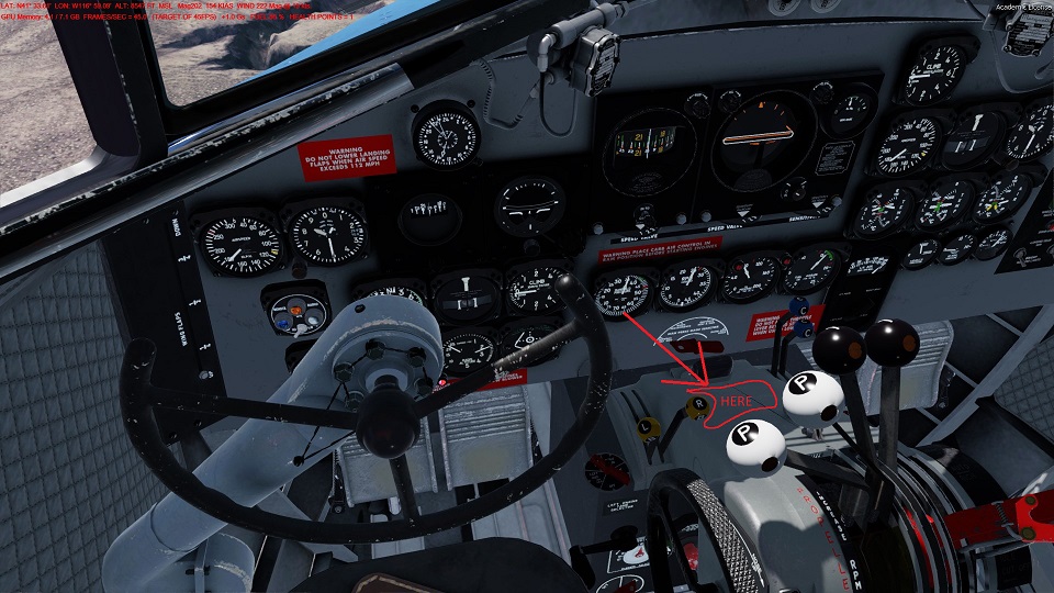
That is all.
I will only ever be, half the Geek that I wished I was.
11/10/2017
This is a guide for Flight Simulator cockpit builders that use Link2FS and Arduino to interface hardware with their simulator to make the migration from Link2FS to using a LUA Script through FSUIPC to do the same thing as Link2FS.
Link2FS is a program put out by a guy named Jim who lives in New Zealand. It allows people to build hardware based on Arduino micro controllers to interface with FSX or P3D flight simulators. Jim has stopped public work on Link2FS so no updates are available for future simulator updates like P3D V4.
LUA is a scripting language that FSUIPC can use to access and change information in FSX and P3D.
LUA can do everything that Link2FS can do and more. Some downsides to LUA are the learning curve and the requirement to have the registered version of FSUIPC. However, if you are a Flight Sim Geek you should probably already have the registered version of FSUIPC. Another downside is there are very few examples of LUA coding for FSUIPC available on the internet, let alone detailed instruction on how the code works. This is something that I hope to help rectify.
I was going to assume that the reader of this has a working Arduino device like a Radio using Link2FS.
I have reconsidered and decided to cater this tutorial to the novice as well.
Hence, this tutorial only covers push buttons, no encoders or displays yet.
You will need the Registered version of FSUIPC.
FSUIPC comes with some PDF documents that can be very beneficial if not required viewing to program your LUA script. These PDFs are, but not limited to: FSUIPC Lua Library, FSUIPC4 Offset Status, The 2016 List of FSX and P3D Controls, Offset Mapping for PMDG 737NGX and Offset Mapping for PMDG 777X.
There is another program that is nearly required for finding Control Codes in the simulator and Variables in aircraft in order to manipulate them. This program is called LINDA. LINDA has a number of functions in it but we are primarily interested in the LINDA Tracer function with the LINDA Console. LINDA can be very confusing at first, but hopefully I can cover that in another tutorial.
This tutorial only covers one main thing, one way communication.
It sends data from Arduino to the LUA script in order to change the COM1 radio Standby frequency up or down.
That’s it.
Learning to crawl.
* An Arduino. (Any make should do, UNO, Mega, Leonardo or any of their clones.)
* Two push button switches. (Normal Off, Push On is preferred)
* MicroSoft FSX or Lockheed Martin Prepar3d (P3D)
* The appropriate registered version for your sim of Pete Dowson’s FSUIPC http://www.schiratti.com/dowson.html
* Two files (LUA_Arduino_Tutorial_001_a.ino) and (Tutorial_001_a.lua) located in this zip
NOTE: Both files include extensive instructions in remarks, some of which duplicate what is said here. You can also copy the code directly from this page. I would highly recommend that you download and install Notepad++ for viewing the code and instructional remarks. Notepad++ is also very useful for writing Arduino and LUA code. When viewing or editing Arduino .ino files in Notepad++, go to the Language Menu and select C++ as the Language to get proper format colors. The LUA files should auto select LUA as language.
On the Arduino, hook up one switch to pin 7 and ground and the other switch to pin 8 and ground.
After plugging your Arduino into your PC, in the Arduino IDE software under “Tools”,
be sure to select your specific Arduino Board and correct COM Port. (Remember the COM Port, it comes up later)
Upload this sketch to your Arduino.
To test it, In the Arduino IDE Software go to “Tools” and open Serial Monitor.
When you press the pin 7 button “A02” should print on the Serial Monitor.
When you press the pin 8 button “A01” should print on the Serial Monitor.
/* 11-8-2017Arduino LUA FSUIPC Tutorial 001_aLUA_Arduino_Tutorial_001_a.ino This .ino file is an Arduino sketch to teach the very basics of interfacing Arduino built hardware with FSX/P3D using LUA thru the Registered version of FSUIPC. The LUA companion file for this tutorial is Tutorial_001_a.lua. My goal is to write this for the novice to learn. Some of it is rudimentary. Lesson 001_a Communication from Arduino to LUA: This tutorial only does one thing, one way communication. It sends data from Arduino to the LUA script in order to change the COM1 radio Standby freqency up or down. That's it. Learning to crawl. An Evolutionary Process: Many of us started out using Link2FS to interface Arduino with FSX. More advanced needs have lead some of us to use LUA thru FSUIPC. With this in mind, in much of my code I still use the same String Inputs to send info to the Sim that Jim designed in Link2FS. The benefit being that you can take a working Link2FS Arduino Hardware setup and just tailor a LUA script. It can work with either Link2FS or LUA which helps in debugging and trouble shooting. What you will need: * An Arduino. (Any make should do, UNO, Mega, Leonardo or any of their clones.) * Two push button switches. (Normal Off, Push On is prefered) * MicroSoft FSX or Lockheed Martin Prepar3d (P3D) * The appropriate registered version for your sim of Pete Dowson's FSUIPC http://www.schiratti.com/dowson.html Hardware Instructions: On the Arduino, hook up one switch to pin 7 and ground and the other switch to pin 8 and ground. After pluging your Arduino into your PC, in the Arduino IDE software under "Tools", be sure to select your specific Arduino Board and correct COM Port. (Remember the COM Port, it comes up later) Upload this sketch to your Arduino. To test it, In the Arduino IDE Software, go to "Tools" and open Serial Monitor. When you press the pin 7 button "A02" should print on the Serial Monitor. When you press the pin 8 button "A01" should print on the Serial Monitor. */ //***************************************************************** //***************************************************************** // The Variables unsigned long time; // Used in a timer for debouncing a noisy switch unsigned long last_time[20]; // also used for debouncing int debounce_time = 250; // We set to 250ms (1/4 of a sec). This prevents the // switch from "double tapping" inside 1/4 of a sec int current_pin; // As the code cycles thru pins this variable gets assigned that pin int current_pin_state; // The state of an individual pin being processed int current_pin_old_state[20]; // The previous state of an individual pin being processed for comparison // NOTE: the two variables with [n], last_time[20] and current_pin_old_state[20] // These are Array variables. Up here we declare them with the potential to have // 20 diff variables indexed 0-19. So...last_time[0],last_time[1],last_time[2].....on up to last_time[19]. // In this sketch we are using only 2 of the 20. The ones associated with numbers 7 and 8. // I put the array at 20 so that you can experiment and add more lines of code without changing too much. // Copy, Paste, Rinse, Repeat. //***************************************************************** //***************************************************************** void setup() { for (current_pin = 2; current_pin <= 10; current_pin++) // Get all the pins ready as inputs { pinMode(current_pin, INPUT_PULLUP); // By setting the pins as INPUT_PULLUP it makes them all "HIGH" // This lets us use buttons without the need for a "pull up" resistor. // Because we made the pins base state to be HIGH when the button is pressed // the pin will be grounded and fall to LOW. current_pin_old_state[current_pin] = digitalRead(current_pin); // We set the current state of the buttons for comparison later } Serial.begin(115200); // opens serial port, sets data rate to 115200 bps with the PC }//end of setup //***************************************************************** //***************************************************************** void loop() // The main program loop, not a lot here just sets the time variable and launches { // a Function...repeatedly, forever. time = millis(); // This is used to get the current clock time in milliseconds and is // used in debounce. INPUTPINS(); //Calls the function INPUTPINS() where we check the buttons for "presses" }//end of void loop //***************************************************************** //***************************************************************** void INPUTPINS() // Buttons are checked for changes { for (current_pin = 2 ; current_pin <=10; current_pin++) // Going to cycle thru all input pins 2-10 { current_pin_state = digitalRead(current_pin); // Get the "state" of the current pin. As it cycles thru, "current_pin" changes. // "State" is whether the pin is HIGH or LOW depending on if the button is pressed. // The first time thru, digitalRead(current_pin) is seen as digitalRead(2). // The second time thru digitalRead(current_pin) is seen as digitalRead(3) and so on. if (current_pin_state != current_pin_old_state[current_pin])// compare the state of the current pin to its previous state { // if the states are not the same, then continue. //*************************************************************************************** if (current_pin == 7) // If the pin is 7 then continue. { if (time - last_time[current_pin] > debounce_time) // If the time from the loop minus "last_time[7]" is greater than 250ms { // then continue if (current_pin_state == LOW ) // If its LOW then the button has been pressed. { Serial.println ("A02"); // "A02" is the Com1 Standby Mhz up code from Link2FS } last_time[current_pin] = millis(); // Reset "last_time[7]" } } //*************************************************************************************** if (current_pin == 8) // If the pin is 8 then continue. { if (time - last_time[current_pin] > debounce_time) // If the time from the loop minus "last_time[8]" is greater than 250ms { // then continue if (current_pin_state == LOW ) // If its LOW then the button has been pressed. { Serial.println ("A01"); // "A01" is the Com1 Standby Mhz down code from Link2FS } last_time[current_pin] = millis(); // Reset "last_time[8]" } } //*************************************************************************************** }// End of IF Current Pin State Check current_pin_old_state[current_pin] = current_pin_state; // Records the current pin state for comparison the next time thru }// End of 'for' loop }// End of INPUTPINS() Function //********************************************************* //*********************************************************
* Place this file in the Modules folder of your sim with the other FSUIPC files
* Have the COM port of the Arduino handy you will need to enter it on first launch
* In P3D go to Add-ons
* Select FSUIPC
* Select Buttons and Switches Tab
* Press a button on your joystick to assign a launch button
* Tick the “Select for FS control” box
* In the drop down “Control sent when button is pressed”
* Scroll down and select “Lua Tutorial 001 A”
* NOTE: NOT LuaClear, LuaSet, LuaDebug
* You can set another button for “LuaKill Tutorial 001 A”
* Hit OK
* Back in the sim, press the Joystick button that you asigned
* Enter the COM port when requested
* Afterward it should remember the COM port on future launches
* Press the buttons on the Arduino and Com 1 radio Standby Mhz should go up and down.
--11-8-2017
--http://thegeekforge.com/2017/11/10/arduino-lua-fsuipc-tutorial-001_a/
--
--Tutorial_001_a.lua
--
--This .lua file is script to teach the very basics of interfacing
--Arduino built hardware with FSX/P3D using LUA thru the Registered version of FSUIPC.
--The Arduino companion file for this tutorial is LUA_Arduino_Tutorial_001_a.ino.
--My goal is to write this for the novice to learn. Some of it is rudimentary.
--
--Lesson 001_a Communication from Arduino to LUA:
--This script only does one thing. It receives data from Arduino
--in order to change the COM1 radio Standby freqency up or down.
--That's it.
--Learning to crawl.
--
-- You Will Need:
-- The appropriate registered version for your sim of Pete Dowson's FSUIPC
-- http://www.schiratti.com/dowson.html
--
-- Instructions To Launch the script:
-- * Place this file in the Modules folder of your sim with the other FSUIPC files
-- * Have the COM port of the Arduino handy you will need to enter it on first launch
-- * In P3D go to Add-ons
-- * Select FSUIPC
-- * Select Buttons and Switches Tab
-- * Press a button on your joystick to assign a launch button
-- * Tick the "Select for FS control" box
-- * In the drop down "Control sent when button is pressed"
-- * Scroll down and select "Lua Tutorial 001 A"
-- * NOTE: NOT LuaClear, LuaSet, LuaDebug
-- * You can set another button for "LuaKill Tutorial 001 A"
-- * Hit OK.
-- * Back in the sim, press the Joystick button that you asigned
-- * Enter the COM port when requested.
-- * Afterward it should remember the COM port on future launches
-- * Press the buttons on the Arduino and Com 1 radio Standby Mhz should go up and down.

------------------------------------------------------------------
---- Variables ---------------------------------------------------
------------------------------------------------------------------
port_file = "Tutorial_001_a_PORT.txt"
speed = 115200
handshake = 0
----End of Variables section -------------------------------------

------------------------------------------------------------------
---- Com Port set up and recording.  AKA the Magic section -------
------------------------------------------------------------------
-- Not going to go into this section other than to tell you it will
-- prompt you for the arduino com port and record it in a text file
-- that it places in the Modules folder.
file = io.open(port_file, "r")
if file == nil then
	port_number = "10"
	file = io.open(port_file, "w")
	io.output(file)
	io.write(port_number)
	io.close(file)
	Arduino_Com_Port = com.open("COM"..port_number, speed, handshake)
else
	port_number = file:read (2)
	--ipc.display(port_number)
	io.close(file)
	Arduino_Com_Port = com.open("COM"..port_number, speed, handshake)
end
if Arduino_Com_Port ~= 0 then
	ipc.display("Arduino Com Port "..port_number.." Open",5)

else
	ipc.display("Could not open ARDUINO Com Port")
	ipc.sleep(2000)
	port_number = ipc.ask('\n'..'\n'..'\n'..'\n'..'\n'..'\n'..'\n'..'\n'.." Enter the Arduino Com Port for Your RADIO")
	file = io.open(port_file, "w")
	io.output(file)
	io.write(port_number)
	io.close(file)

	Arduino_Com_Port = com.open("COM"..port_number, speed, handshake)

	if Arduino_Com_Port == 0 then
		ipc.display("Could not open ARDUINO Com Port",5)

		ipc.exit()
	else
		ipc.display("Arduino Com Port "..port_number.." Open",5)

	end
end
---- End of Magic section ----------------------------------------


------------------------------------------------------------------
---- Functions ---------------------------------------------------
------------------------------------------------------------------
-- Only one function in this script.
-- When data comes in from the Arduino, it gets sent to this
-- function.  When it finds one of the strings in "" it does that
-- ipc.control.
function Arduino_Data(Arduino_Com_Port, datastring, length)

	---- COM1 Standby Freq -------------------------------------
	if (string.find(datastring, "A02")) then
		ipc.control(65637,0)  --This is the control to move Com1 Stby Mhz up
	end
	if (string.find(datastring, "A01")) then
		ipc.control(65636,0)  --This is the control to move Com1 Stby Mhz down
	end
	if (string.find(datastring, "A04")) then
		ipc.control(65639,0)  --This is the control to move Com1 Stby Khz up
	end
	if (string.find(datastring, "A03")) then
		ipc.control(65638,0)  --This is the control to move Com1 Stby Khz down
	end
			-- What are control numbers in "ipc.control" and where do I find them?
			-- In the FSUIPC Docs there is a PDF with a list.
			-- Also a program called LINDA has function called Tracer.
			-- Tracer has Controls as well as Lua Variables for specific Aircraft
			-- Another way to manipulate the sim is thru offsets. Some are read only,
			-- others you can write to.
end  -- function end
---- End of Functions section -----------------------


-----------------------------------------------------
---- Events -----------------------------------------
-----------------------------------------------------
-- Events are awesome. They dont require a continuous loop to work.
-- They just sit back and wait for a trigger and then spring into action.
-- Events must go at the bottom of the script. Why? Google it.

event.com(Arduino_Com_Port, 50,1, "Arduino_Data")
	-- This is event.com, it listens for data on the Arduinos Com port.
	-- The 50 and 1 are the max and min characters accepted
	-- The data is then passed to the "Arduino_Data" function above.


---- End of Events section --------------------------
You may have notice in the LUA file, that there is code to also change the Khz of the COM1 Standby radio.
However, I did not include the corresponding code in the Arduino Sketch.
I left that for the novice to experiment with.
Just hook up a couple more buttons to the Arduino on some of the other pins between 2 and 10.
Then add the extra code to the Arduino Sketch to make it work.
You won’t have to change anything on the LUA script.
If you happen to have more than one Arduino connected to your PC and you accidentally enter the incorrect COM Port of the Arduino when launching the LUA script, it can cause the script to connect to the wrong Arduino. To fix this and get connected to the correct Arduino, you can delete the “Tutorial_001_a_PORT.txt” file from your Modules folder and relaunch the script and then enter the correct port when prompted. Alternatively, you can manually edit that file and put in the correct COM Port number.
I apologize for any typos errors and omissions.
If you see any errors, leave a comment and I might fix it.
I may periodically edit this to improve quality.
~Fess
If you do any coding on a Windows PC, then you probably already know about Notepad++.
If you are just entering the world of coding, whether it be HTML, PHP, C, C++, C#, LUA, JAVA, RUBY, and the rest, then you need to at least try Notepad++.
Don’t let the name fool you, this is not your Grandpa’s Windows “Notepad”.
Notepad++ is a source code editor with syntax highlighting among many other functions.
I have been using Notepad++ for a number of years for HTML and PHP web work. I have also used it with the Arduino IDE to make Arduino Sketches. Notepad++ has been in constant development with oodles of buzzers, bells and whistles being added to it over the years.
For my limited needs and usage, I really haven’t scratched the surface of its capabilities. I did find its search and replace function very useful when needing to change every instance of a variable name.
Notepad++ is free and distributed under GNU General Public Licence. There are no crapware toolbars distributed with it.
You can check it out here. http://notepad-plus-plus.org/
A few folks have asked me how to connect a MAX7219, 8 Digit, 7 Segment, Tube Display Module to an arduino and code it to display information from Flight Simulator X (FSX) via Link2FS.
Below are pictures and explanation of one way to set this up.
At the bottom of this article is a working but limited Arduino Sample Sketch that will only display the Autopilot Altitude Set from FSX via Link2FS. The Arduino Code has been mostly stripped down to this one function for simplicity and is remarked heavily for educational purposes.
In the picture above I am using an Arduino Leonardo Clone. An Uno or Mega will also work.
To connect the MAX7219 to the Arduino, we use 5 wires connected to the 5 pins on the left side of the module. Three of them are for communication and two are for 5 Volt and Ground connections.
In this particular example I use pins 10, 11, and 12. If you compare the wire colors in the picture below with the picture above, you will see Orange, Data (DIN) is connected to pin 12, Yellow, Load (CS) is connected to pin 11, and Green, Clock(CLK) is connected to pin 10.
Red and Brown are connected to 5Volt (VCC) and Ground (GND), respectively.
The Modules have another set of pins on the right side of the Printed Circuit Board (PCB), that are labeled nearly identical to the left side. The right side pin labels are on the backside of the PCB. They are VCC, GND, DOUT, LOAD, CLK. If you have more than one module that you want to “chain” together then you do it through these pins. The second module’s left side, DIN, CS, and CLK would go to the first modules right side DOUT, LOAD, and CLK.
NOTE: Do NOT chain the VCC 5Volt and GND from one module to another. As I understand it there is a diode in each module that will drop the voltage on the out going side. It may work ok with 2 or 3, but if you chain more you may be looking at dimming digits or failure to function. So, it’s easy enough to run the 5Volt and Ground to a common bus from the Arduino.
In the picture below you can see we are connected to Link2FS and receiving the Autopilot Altitude Set as it is present on the display.
In the above picture you can see what Link2FS sends to the Arduino when the Autopilot Altitude Set is at 18000.
=b18000
First the Arduino Code looks for the “=”.
After finding the “=” it checks the next character and find a “b”.
The “b” tells the “Switch Case” in the code to start storing and display the Autopilot Altitude set “18000”.
The picture above is just to show how the displays can be tethered away from the module. On my first go, I used male/female jumpers. I found that the female connection to the displays would sometimes become loose and subject to vibration making the connection intermittent. This would result in some or parts of the display digits to flicker or go off completely. Jostling the wires would cause it to work again. This picture has soldered connections on the display side, with heat shrink covering.
Pictured above is the type of jumper wires needed to tether the displays away from the module.
The leads have round male connectors.
NOTE: Dupont brand wire jumpers with square male connectors that work fine with Arduinos, will not fit the female connection on the Max7219 display module.
The picture below:
If you find the need to do a lot of soldering and cover the connections with heat shrink, it is far cheaper to buy heat shrink by the 100ft spool.
I used 3/32 for the above wires. I found the 100 foot spool on ebay for about $13 US.
/*
This is a simple demonstration of code to Display information on a MAX7219 8 Digit 7 Segment Tube Display Module.
The Information is extracted from Flight Sim X via a program called link2fs_multi and then sent to the arduino.
There are snippets in this code that came from Jim, the author of Link2FS.
Find him at jimspage.co.nz. Also, in the mycockpit.com forums under link2fs.

This example will only work with FSX's default Auto Pilot.
Some planes like PMDG's 737 does not use FSX's default variables.
I use an Array variable to store the Auto Pilot Altitude Set Display.
Its probably not necessary, but its what I used in my Radio Box for quicker updates when using
shared displays with a Mode/Function Selector knob.
              *****************************************
              ***** Info on how the Displays work *****
              *****   This is an excerpt from my  *****
              *****        Radio Box Code         *****
              *****************************************
      led_Display_1.setDigit(0,7,Com1Active[0],false);    // setDigit(0,7,Com1Active[0],false) The 0 is the first display, 7 is the first character in the
      led_Display_1.setDigit(0,6,Com1Active[1],false);    // display, Com1Active[0] is the stored Integer to be displayed, false is no decimal point.
      led_Display_1.setDigit(0,5,Com1Active[2],true);     // "true" puts in the decimal point
      led_Display_1.setDigit(0,4,Com1Active[3],false);    // setDigit is for putting in numbers
      led_Display_1.setDigit(0,3,Com1Active[4],false);    // You can also use setChar for putting in some letters
                                                          // character, symbols, and ' ' space.
                                                          // NOTE: setChar has to use single quote 'A'
                                                          // Double quote "A", is for Strings and wont work.

      ****************** The 300 Level Remarks ****************************************
       In the "300 Level Class", you can use setRow to light one of the 7 segment
       displays using binary or hex equivalent. It would look like this:
       led_Display_1.setRow(1,4,B00110000,false) that would display the number 1.

                __A_      The segments on my displays are lettered A thru H
              F|    |B    However, using the setRow with Binary the H (decimal point) comes first.
               |__G_|             If you want an 8 with no decimal...
              E|    |C             H A B C D E F G
               |__D_|.H          B 0 1 1 1 1 1 1 1   = 8
                                 B 0 1 1 1 0 0 0 0   = 7

      *********************************************************************************

*/


#include "LedControl.h"
                               // ******   LedControl Library is required to drive the MAX7219 7 segment LED displays.  *******
                                                    // led_Display_1 is the variable name of my set of displays chained
LedControl led_Display_1 = LedControl(12,10,11,8);  // together running off of pins 12,11,10.
                                                    // Pin 12 is the DataOut
                                                    // Pin 11 is Load or CS
                                                    // Pin 10 is clock.
                                                    // The 8 is for how many displays you have to chain.
                                                    // I have 4 but put 8 incase of expansion. It cost no memory.
                                                    // You can run any pins you want in the instruction,
                                                    // just plug the module in correctly.
                                                    // LedControl(Data,Clock,Load,Displays)
                                                    // I used 12,10,11 so I could have a straight ribbon connection
                                                    // from the module without crossing leads.


int CodeIn;      // used on all serial reads from Jim's code
String Digit;    // Variable as a string to take from getChar()
int Count;       // This variable used in loops in the EQUALS() function
int AP_alt_set[5];   // AP_alt_set[5] is an array of the 5 digits that are the Auto Pilot Altitude Set


//**********************************************************
//*************( START of void setup() )********************

void setup()
{
    //The MAX72XX is in power-saving mode on startup, we have to do a wakeup call
    delay (500);
    led_Display_1.shutdown(0,false);      // I have 4 displays, these start them up
    // delay (500);                          // I put the delay in so they all dont start drawing
    // led_Display_1.shutdown(1,false);      // current at the same time.
    // delay (500);                          // I had an issue with running on only USB power and getting a display glitch.
    // led_Display_1.shutdown(2,false);      // The delay seems to have fixed this issue.
    // delay (500);
    // led_Display_1.shutdown(3,false);

    // Set the brightness to a lower than medium values
    led_Display_1.setIntensity(0,8);
    // led_Display_1.setIntensity(1,8);
    // led_Display_1.setIntensity(2,8);
    // led_Display_1.setIntensity(3,8);

    // and clear the display
    led_Display_1.clearDisplay(0);
    // led_Display_1.clearDisplay(1);
    // led_Display_1.clearDisplay(2);
    // led_Display_1.clearDisplay(3);

    Serial.begin(115200);
}
//**************( END of void setup() )********************
//*********************************************************


//*********************************************************
//*************( START of void loop() )********************

void loop()
{
    if (Serial.available())
    {
        CodeIn = getChar();
        if (CodeIn == '=')
        {
            EQUALS();              // The first identifier is "="
        }
   // if (CodeIn == '<') {LESSTHAN();}// The first identifier is "<"
   // if (CodeIn == '?') {QUESTION();}// The first identifier is "?"
   // if (CodeIn == '/') {SLASH();}// The first identifier is "/" (Annunciators)
  }
}
//*****************( END of void loop )********************
//*********************************************************


//*********************************************************
//************( START of getChar() Function )**************

char getChar()// Get a character from the serial buffer
{
  while(Serial.available() == 0);   // wait for data
  return((char)Serial.read());      // Thanks Doug
}
//***************( END of getChar Function )***************
//*********************************************************


//*********************************************************
//*************( START of EQUALS() Function )**************

void EQUALS()               // The first identifier was "="
{
    CodeIn = getChar();     // Get another character
    switch(CodeIn)          // Now lets find what to do with it
    {
        case 'b':           //  AP altitude set
            Count = 0;               // clear the Count
            while (Count < 5)        // we will count to 5 from 0 to 4
            {
                Digit = "";          // clears the string variable Digit
                Digit += getChar();  // Makes the string Digit what ever getChar() is holding

                AP_alt_set[Count] = Digit.toInt(); // Turns the string Digit into an Integer and
                                                   // then stores it in the Array AP_alt_set[] 0,1,2,3,4
                Count++;
            }

            led_Display_1.setDigit(0,4,AP_alt_set[0],false);   // First digit of Alt Set is displayed
            led_Display_1.setDigit(0,3,AP_alt_set[1],false);   // Second digit of Alt Set is displayed
            led_Display_1.setDigit(0,2,AP_alt_set[2],false);   // Third digit of Alt Set is displayed
            led_Display_1.setDigit(0,1,AP_alt_set[3],false);   // Fourth digit of Alt Set is displayed
            led_Display_1.setDigit(0,0,AP_alt_set[4],false);   // Fifth digit of Alt Set is displayed
                                                               // false denotes NO decimal point
        break;
/*
    ******************************************************************************
    *********  REMARKED OUT EVERYTHING EXCEPT AUTO PILOT ALTITUDE SET ************
    *********    IF YOU TRY TO USE THE BELOW CODE IT WILL NOT WORK    ************
    *********        IT HASNT BEEN FULLY SET UP IN THIS SAMPLE        ************
    ******************************************************************************
        case 'c':    //  AP vertical speed set
            Count = 0;
            while (Count < 4)
            {
                Digit = "";
                Digit += getChar();

                if (Count == 0)
                {
                    if (Digit == "-")
                    {
                        AP_vs_minus = '-';
                    }
                    else
                    {
                        AP_vs_minus = ' ';
                    }
                    Digit = "";
                    Digit += getChar();
                }

                AP_vs_set[Count] = Digit.toInt();
                Count++;
            }
                led_Display_1.setChar(2,4,AP_vs_minus,false);
                led_Display_1.setDigit(2,3,AP_vs_set[0],false);
                led_Display_1.setDigit(2,2,AP_vs_set[1],false);
                led_Display_1.setDigit(2,1,AP_vs_set[2],false);
                led_Display_1.setDigit(2,0,AP_vs_set[3],false);
        break;

        case 'd':    //  AP heading set
            Count = 0;
            while (Count < 3)
            {
                Digit = "";
                Digit += getChar();

                AP_hdg_set[Count] = Digit.toInt();
                Count++;
            }
            if (AP_hdg_set[0]==0 and AP_hdg_set[1]==0 and AP_hdg_set[2]==0)
            {
                AP_hdg_set[0]=3; AP_hdg_set[1]=6;
            }
            led_Display_1.setDigit(1,6,AP_hdg_set[0],false);
            led_Display_1.setDigit(1,5,AP_hdg_set[1],false);
            led_Display_1.setDigit(1,4,AP_hdg_set[2],false);
        break;

        case 'e':    //  AP course set
            Count = 0;
            while (Count < 3)
            {
                Digit = "";
                Digit += getChar();

                AP_crs_set[Count] = Digit.toInt();
                Count++;
            }
            if (AP_crs_set[0]==0 and AP_crs_set[1]==0 and AP_crs_set[2]==0)
            {
                AP_crs_set[0]=3; AP_crs_set[1]=6;
            }

            led_Display_1.setDigit(0,7,AP_crs_set[0],false);
            led_Display_1.setDigit(0,6,AP_crs_set[1],false);
            led_Display_1.setDigit(0,5,AP_crs_set[2],false);

            led_Display_1.setDigit(3,6,AP_crs_set[0],false);
            led_Display_1.setDigit(3,5,AP_crs_set[1],false);
            led_Display_1.setDigit(3,4,AP_crs_set[2],false);
        break;

       //etc etc etc
       // You only need the "Case" testing for the identifiers you expect to use.
    ******************************************************************************
    *********  REMARKED OUT EVERYTHING EXCEPT AUTO PILOT ALTITUDE SET ************
    ******************************************************************************  */
    } // ***  End of Switch Case ***
}
//***************( End of EQUALS() Function )**************
//*********************************************************
August 5, 2014
This project was conceived and started with the ordering of parts around Sept-Oct, 2013.
Functional construction and coding was completed mid Nov, 2013.
A friend and I worked on this together. He was also building a radio. His was a bit different than mine with a smaller footprint for a fighter cockpit setup.
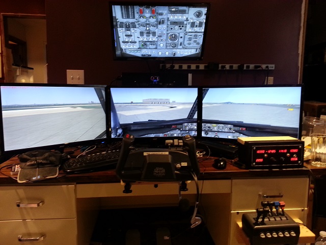 If you are an ate-up, Flight-Sim geek, then you may have a setup similar to that above.
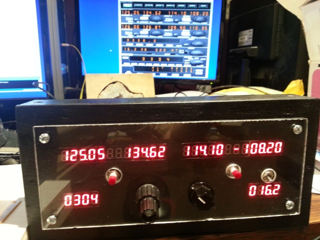
In the picture we have MicroSoft Flight Simulator X (FSX), CH Yoke, CH Throttle Quadrant, CH Rudder Pedals (on the floor), three 24 inch displays in span view, a single 21.5 inch overhead display, TrackIR (head tracking device), and on the right side of the desk, lit up with red 7-segment displays, is a custom built Radio Stack of which this article is about.
 Here is a close up with a $1 bill for scale.
This project would not have been possible without a software interface program that allows Arduino cards to talk to FSX. The program is called Link2fs and was written by a man named Jim who lives in New Zealand. I have been following Jim at jimspage.co.nz for a number of years. He has built at least two incarnations of a flight simulator motion platform.
A motion platform is the dream.
I had dabbled a bit, in the past, with Arduino. Once I built an interface for a recumbent stationary bike-to-PC using an Arduino, a magnetic reed switch, and a game controller. It allowed the user to run in first person shooter games by pedaling the bike.
When I read that Jim had discovered Arduino and he had written the Link2FS interface software to talk to FSX, I had to give it a shot.
Let me warn you…
If you start down this path of building interface devices for Flight Simulator, it is a dark path and it never ends. Each new buzzer, bell, or whistle that you make will give you a “discovery and accomplishment” high. It will make you feel as if there is nothing you can’t do. But the high is fleeting. It does not last. You will soon become discontent with the status quo. Then you start thinking, “Well it would be easy to add this or to add that.” It won’t stop until you have a full scale replica cockpit consuming substantial square footage of living space in your home. If your family is lucky, you prefer small general aviation aircraft over commercial jets.
The first thing I needed to do before ordering some of the more pricey parts was some proof of concept testing. I had downloaded Jim’s software and had confirmed that it did indeed connect to FSX and could change things, like radio frequencies.
Next, I hooked up a simple push button switch on an Arduino clone and modified some of Jim’s example code, to make the switch change one of the radio frequencies in one direction.
That’s all it did, you press the button and the Mhz go up by one tick.
As simple as it was, it gave me the first rush.
One of the other things I did, not pictured, is wire up some LEDs as Landing Gear status lights and used some more of Jim’s sample code to make them work. By experimenting with the Link2FS software and different Arduino code, it allowed me to learn more about the nuance and communication relationship of FSX to Link2FS and Link2FS to Arduino.
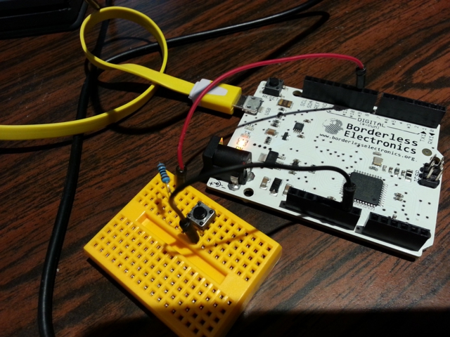 Arduino Leonardo Clone with simple push button switch.
Pictured below is a snapshot of an older version of Jim’s Link2fs_multi program. It is the program that interfaces FSX to Arduino. It is the middle man, that sends and receives from FSX and also sends and receives from Arduino. The “multi” version allows you to control multiple Arduinos with one instance of the Link2fs program. Need more Arduinos than one instance can handle? Not a problem. You can also run multiple instances of Link2fs_Multi.
FSX <-> Link2FS <-> Arduino.
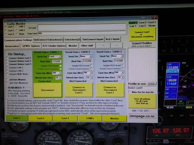 Link2fs_Multi, interface program for FSX to Arduino.
Now that I have proved that it is possible to change things in FSX from an Arduino, it is time to start finding components to build a Radio Stack.
Many different aircraft avionics utilize “Dual Concentric Rotary Encoders”. These are basically 2 dials in one. Elma makes a good one in the E37. Unfortunately, they aren’t cheap and they aren’t easy to come by. There is one guy on the planet, that I know of, that sells them in single quantities and that’s Leo at leobodnar.com in the UK. At the time of this writing one E37 with knobs, from Leo, shipped to the US via Royal Mail Airmail would be $40.26 USD. In Dec of 2013, I had enquired at Elma to see what I could get if I wanted to buy bulk. At 100 units they would cost $17.50 per each not including knobs.
I bought three E37s from Leo, one for me, one for a friend and one for a spare or future project.
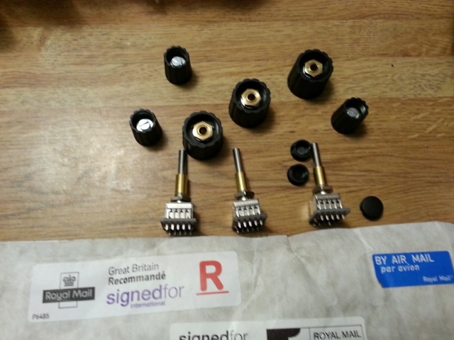 Elma E37 Dual Concentric Rotary Encoders.
Since I didn’t want to drop big money for multiple Encoders, I decided to use a Rotary Switch as a function selector on the Radio. You dial the function you want with the switch and then use the encoder to change the frequency.
Functions that I coded in were: COMM/NAV 1, COMM/NAV 2, TRANSPONDER, ADF, and a limited AUTO PILOT function for experimentation.
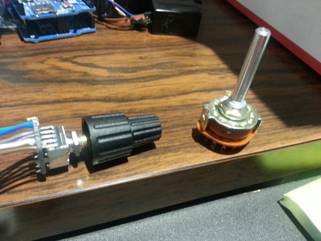 Rotary Encoder on the left. Rotary Switch on the right.
The Elma E37 Rotary Encoders are not plug-and-play. They come with a small Printed Circuit Board (PCB) that needs to be soldered to the encoder. The PCB has marked pinout holes in it that allows you to also solder wire leads to it.
When I first coded the Arduino to work with the Encoder, again taking Jim’s sample code and modifying it for my purpose, I got the accomplishment rush again, “I am turning a knob and the frequencies in the sim are changing! So cool, so cool!” When I showed it to my friend, his response was a satisfied, “Ok, that’s perfect. I’m done.” As if that is all he needs to make him happy, he needs no more. But no, that was just his first “high“. We didn’t even have the 7-Segment Displays yet.
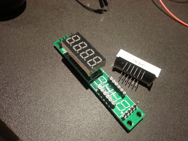 MAX7219 8-Digit 7-Segment Tube Display Module
While looking for a 7-segment LED display solution, I came across a number of possibilities.
Some were serial driven modules that had 16 digits. I had also seen other folks actually drive multiple single digit 7-segment displays by multiplexing outputs on Arduino. An incredible accomplishment with an insane amount of wires but way too complex for me. Plus it uses too many Arduino input/output pins.
I finally stumbled onto the MAX7219 8-Digit 7-Segment Tube Display Module. The chip on the Module is the MAX7219 which is the driver for the displays. In short, it receives a serial instruction, displays what the instruction told it to display, and holds that display until told to do otherwise.
These displays work with the LedControl library for Arduino.
The beauty of these display modules is that they are comprised of two 4-digit displays that are not soldered to the board. They are in sockets. This got me to think that I can tether these displays with wires and place them any where I want to on my radio without the PCB getting in the way.
The other great thing about these displays is that you can chain up to eight of them together and only have to use three pins on the Arduino.
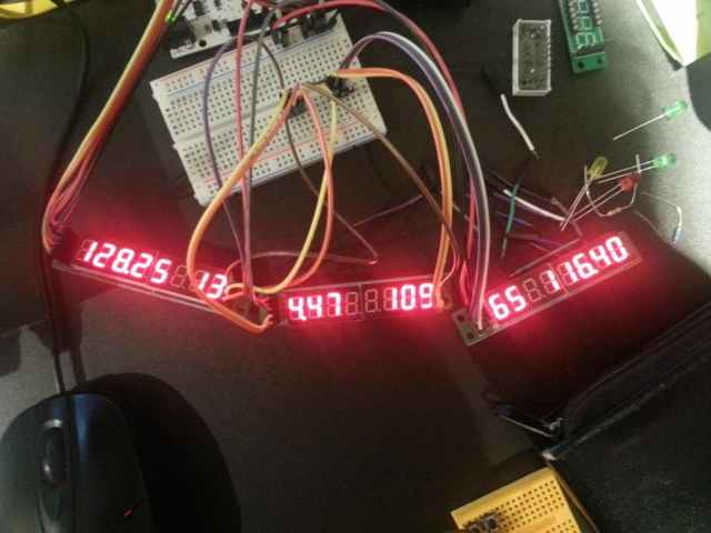 3 MAX7219 Display Modules chained together for testing, pre tethering.
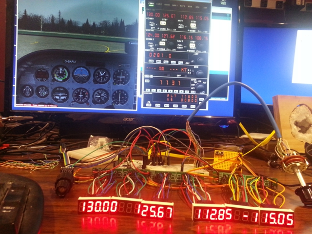 Here are 3 MAX7219 Modules with the 7-Segment Displays tethered away from the boards.
Also pictured is the Rotary Encoder, Rotary Switch and Arduino and experiment board for wire junctions behind the Modules.
The hardware and software are now working together. We need to get all of those wires in a box.
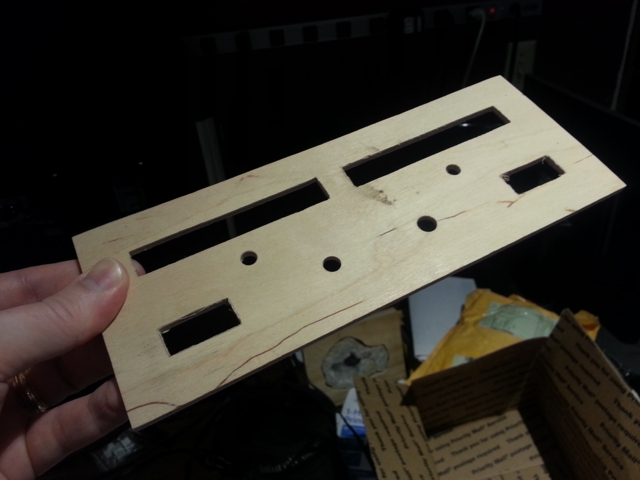 This is the face plate that my friend helped me come up with.
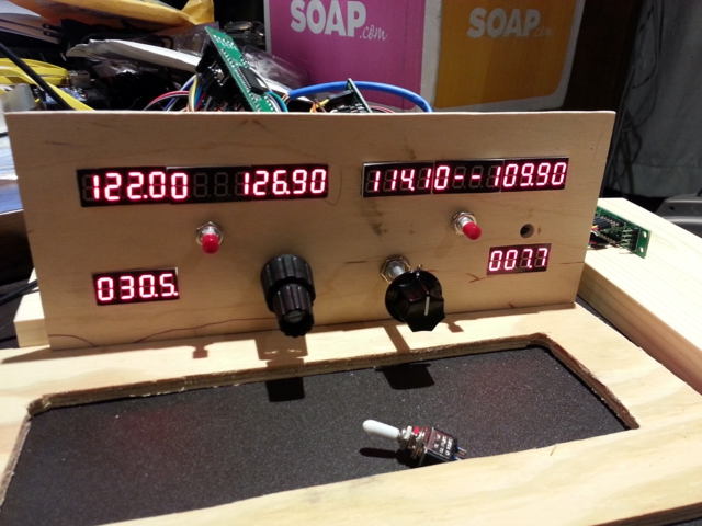 The rough fit. I added a 4th MAX7219 Display Module for Transponder and DME.
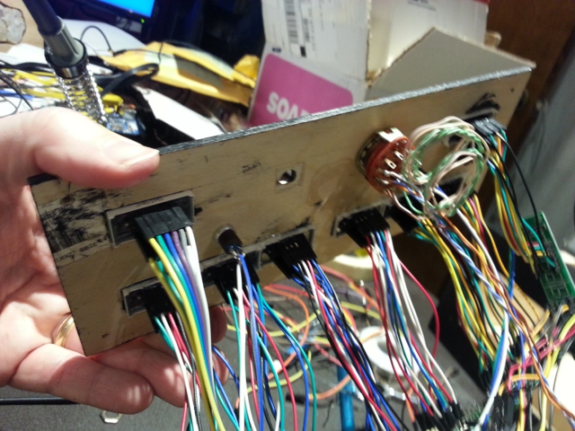 The back side fitting after paint had been applied.
 Lexan cover for the face plate.
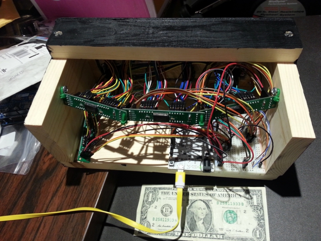 Backside with a dollar bill for scale.
Acceleration on the Encoder and updated functions.
After months of use and testing, some things I would do differently…
The female end of the tether wires on the 7-segment displays doesn’t cut the mustard. Sometimes, from movement, the segments on the displays will flicker because of the female ends slipping. A little jostling and they work. To do it better, the tether wires need to be soldered to the 7-segment displays. The other end of the tether wire can still be plugged into the MAX7219 Module without problem.
I am planning on designing and building a new Radio Stack with multiple displays and multiple encoders instead of sharing the main display and encoder with multiple radios.
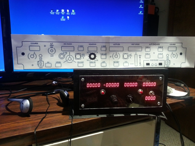 Scale print out of the next project, a Mode Control Panel (MCP)/Auto Pilot for a Boeing 737.
May 30, 2014
Good golly, it’s been almost a year since my last post. I blame apathy. Last November I built a Radio Stack for Flight Simulator X (FSX). It uses an Arduino Leonardo clone, and third party software called “Link2FS_Multi”.
I didn’t have to use a clone, its just what I had on hand.
Other parts used:
4 MAX7219 display modules to drive the 7 segment displays
1 Elma E37 Dual Concentric Rotary Encoder with push button
2 Momentary Push Switches
1 Toggle Switch
1 Rotary Switch
After the Radio Stack, I got cocky and started work on a 737 style MCP/autopilot.
It uses the same type of interface, Link2FS_Multi to talk to FSX, but this time I used an Arduino Mega.
As of this writing the MCP is still under construction, but is partially functional.
I plan to program it to work with the PMDG 737NGX. Not a walk in the park, as PMDG uses proprietary offsets with their aircraft. Fortunately they publish the offsets.
I NEED TO…
I need to document these projects with more photos and detailed explanation.
June 28, 2013
I am not an expert.
I am just a hack.
I do not understand all of the code nuance.
I take what others have done, substitute my variables and modify the code to my requirements.
There are a million ways to skin a cat.
This is one way that I have muddled through.
I don’t go into how to set up a MySQL data base, try google.
#include <SPI.h>
#include <Ethernet.h>


int bstate = 0;         // This is the variable we will send, but it will be formated as String first.
String txData ="";      // This is the Data that will be sent to the PHP page. It will have variable names and data in it.

                        // Local Network Settings
                        // My mac 90-A2-DA-0D-83-9D Must be unique on local network
                        // (should be on the back of ethernet shield)
byte mac[]     = { 0x90, 0xA2, 0xDA, 0x0D, 0x83, 0x9D };

byte ip[]      = { 192, 168,   1,  199 };       // Must be unique on local network
byte gateway[] = { 192, 168,   1,  1 };         // I left these in for reference in case you need them
byte subnet[]  = { 255, 255, 255,   0 };        // I left these in for reference in case you need them


void setup()
{
     Ethernet.begin(mac, ip); // Mine works with just the mac and ip. Gateway and DNS may be needed.
                              //Depending on your router setup, you may need to
                              // reference http://arduino.cc/en/Reference/EthernetBegin


     Serial.begin(9600);      // Just for output so we can see if its working
     delay(1000);
}

void loop()
{
     bstate++;               //  This just adds one to the variable "bstate" each time thru the loop. I just did this for testing
                             // I send the data as a String. I read about some having difficulties sending integers.
                             // 'txData' is a string that is sent to the PHP page.

     txData = "BUTTON_STATE="+ (String (bstate));

                              // 'BUTTON_STATE' is the POST variable that the PHP page is looking for.
                              // The '+' puts the string parts together.
                              //  '(String (bstate))' formats 'bstate' from a numerical value to a string.
                              // Multiples would look like
                              //txData = "VARIABLE1="+ (String (var1))+"&VARIABLE2=" (String(var2));

     EthernetClient client;

                                         //("yourwebsite.com",80) could also be, I think an IP, (xxx.xxx.xxx.xxx,80) or
                                         // you could define a variable 'server' like we did with 'ip' and 'mac'
                                         // like this, 'byte server[]  = { xxx, xxx, xxx, xxx }'
                                         // then this line would look like  'if (client.connect(server,80))'

    if (client.connect("yourwebsite.com",80))
    {
         Serial.println("Connected to yourwebsite...");   // This isn't required, just for feedback
         Serial.println();


                                       // HERE IS THE MEAT AND GRAVEY
                                       // The '/update/update.php' is the directory and file you are sending to
                                       // if the file is in the root of the domain it would just be '/update.php'

          client.print("POST /update/update.php HTTP/1.1\n");

                                       //  yourwebsite.com, domain where the php file is hosted

          client.print("Host: yourwebsite.com\n");
          client.print("Connection: close\n");
          client.print("Content-Type: application/x-www-form-urlencoded\n");
          client.print("Content-Length: ");

                                       // Remember our variable txData? It has all of the info we are sending
                                       // to the PHP page, 'update.php'.  BUT, the PHP page needs to know how many characters
                                       // are coming. We give it by using 'txData.length()'

          client.print(txData.length());
          client.print("\n\n");
          client.print(txData);         // after all of the required junk we send the data
    }
    else
    {
         Serial.println("Connection Failed."); // Again the Serial is for feedback.
         Serial.println();
    }
    delay(5000); //this delay was for my test to send a number every 5 sec
}
Next…
Make a PHP file called config.php.
CODE for config.php
<?php

$dbhost = 'localhost'; //mysql server address, it can be an ip address typically it is 'localhost'
                                                // It could look like 'mysqlserver.mydomain.com'
                                                    // To access the mysql database you need a username and password
$dbuser = 'mydatabase_username';
$dbpass = 'mydatabase_password';
$dbname = 'mydatabase_name'; //This is the name of your database on the mysql server

$conn = mysql_connect($dbhost, $dbuser, $dbpass) or die ('Error connecting to mysql');
mysql_select_db($dbname);
?>
AND ‘DEN…
Make a file called update.php
CODE for update.php
<?php
require("config.php");
// You need to create a table on your MySql server database. Here it is called 'MY_TABLE'.
              // You will also have to define fields in the table.
             //I happen to name my fields the same as my POST variables.


$query = "INSERT INTO MY_TABLE(BUTTON_STATE)
                  VALUES('$_POST[BUTTON_STATE]')";


 if(!@mysql_query($query))
{
    echo "&Answer; SQL Error - ".mysql_error();
    return;
}
?>
NOTES
Multiple variables being posted might look like…
$query = "INSERT INTO MY_TABLE(VAR1, VAR2, VAR3)

  VALUES('$_POST[VAR1]','$_POST[VAR2]','$_POST[VAR3]')";
In PHP you can break lines for readability.
End of line or statement is denoted by a semicolon.
May 29, 2013
I had decided to try and document my projects for posterity, and to possibly aid others with similar projects of their own. Hence, this site. The documentation of these said projects, is a project in and of itself. It takes time to take pictures, upload them, and write things about them. It takes even more time to take good pictures, upload them, chronologically display the progress and write coherent things about them. Time is probably my biggest hurdle…next to The Latest PC Game addiction (which eats up time). But also, there is that whole… working a full time job, being the “engineer” that keeps a house of six occupants operational, being a Dad, being a husband, being a car mechanic, being a computer tech, being a plumber, being a contractor, etc.
So far, I have failed at project completion and documentation.
I have ideas. I have experimented with my ideas for proof of concept. If I can focus, pull it together, follow through, get it done, and document it, I think I’ll have something worthy to share.
I will only ever be, half the Geek, I wished I was.
I go by a number of names, Fess_ter_Geek, Fess_ter, Fess, and at work, they call me Fesstus. I’m married with four, home schooled children, seven desktops, and two laptops in the house. I build my own desktops and usually overclock to boost the price/performance ratio.
The first pre-built, store bought, desktop that I purchased was a Packard-Bell 486sx 25Mhz sporting a 5.25in floppy and a 3.5in floppy. It did not come with a CD-Rom drive or a sound card. I had to add those later and I also upgraded the processor which was the start of my computer hardware knowledge that eventually lead me to build my own.
My first exposure to a computer was about 1979 when I was 11 years old. My Uncle Norm, sold computer learning systems to schools. So, as a salesman he had one for demonstration.
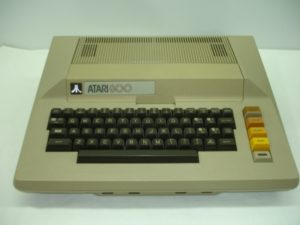
His was an ATARI 800, 8 bit computer. It was big, beige and brown and it was beautiful. When my mother and I would go and visit them, 3 hours away with a “55 stay alive” speed limit, I would stay up until 3 or 4am playing Star Raiders until my eyes bled.
Around 1983-84 my mother relented and spoiled me with an ATARI 800xl of my own. It was a more modern looking machine although, disappointingly, it couldn’t run some of the original 800 software.
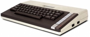
As I recall, some of the older titles could be run by using a “Translator” disk but there were others that wouldn’t run at all. I still have my old 800xl in the closet. Every four or five years or so, when the nostalgia hits me, I pull it out, plug it in, and relive a few old memories. I took that machine to college with me and turned in a crappy paper or two written on ATARI Writer word processor and printed on an ATARI daisy wheel printer. (Whrrrrrr chunk chunk chunk whrrrr)
After college, the procurement of employment, and marriage, I started to get into the “IBM” type of machines or “clones” as they used to be called. Today we call them “PCs” (pee-sees). My wife brought to the marriage, in her dowry, an actual IBM PS2 that cost as much as a used car. It was a 386 16 Mhz and sported the new IBM Micro Channel Architecture, MCA. IBM was going to change the industry with MCA. It was kind of like PCI slots. They were faster and “better” than ISA slots. But, the “industry” thought otherwise and MCA was short lived. The 386 had no sound card, most computers didn’t, and you couldn’t find one for it because there were very few MCA cards around. With no upgrade options this led me to buy the first Packard-Bell.
Over the years as computers got faster and my knowledge grew, I started learning about overclocking. When Intel came out with the Pentium II, their top end was a 450 Mhz processor. I was contemplating building two identical machines, one for my wife and one for me. It was going to cost a “Mint” for two top end processors. Fortunately, my timing and research revealed that Intel’s lower end processor, the Celeron 300a with a smaller on die cache could easily overclock to 450 Mhz and yield identical performance,and in some cases higher, than Intel’s PII 450. That was my first stellar overclock and price/performance, value success. In the years since, my system builds have migration between AMD and Intel systems depending on which one was deemed best at the time for the price/performance ratio. As of this writing I have both AMD and Intel systems running in my house.
In the last couple of years I have started tinkering with Arduino. If you have to ask, Google it.
I have been slowly remodeling my house. If you have ever dug remotely, into a home repair or modification job, you have likely found out that attempting to do one job usually reveals two other things that need fixing.
I like computer games, BF3, Flight Simulator, and others. One of my all time Uber Geek dreams is to build a full motion flight simulator platform. Oh yes, someday it will be mine and I will make it. In the mean time, I intend to learn to interface Arduino with Flight Simulator X via FSUIPC. Speaking of Flight Sim, at one time I was involved with a Virtual Airline on VATSIM and did a lot of PHP web work for our site, learning as I went. Then we had child number 4 and leisure time was gone. I learned just enough PHP/MYSQL to be dangerous but not proficient.
I play guitar, rhythm and chords mostly. If you don’t play guitar, I sound really good. If you do play guitar then, I’m just a hack like all my other “talents”.
Well that’s the start, anyway…